One of the major attractions in model railways for me is the superimposition of signalling and interlocking onto a layout. It’s essentially free added-value to an existing layout, adding complexity and interest (oh how I loathe the use of that term, forgive me).
Here is an early attempt at a signal box diagram:
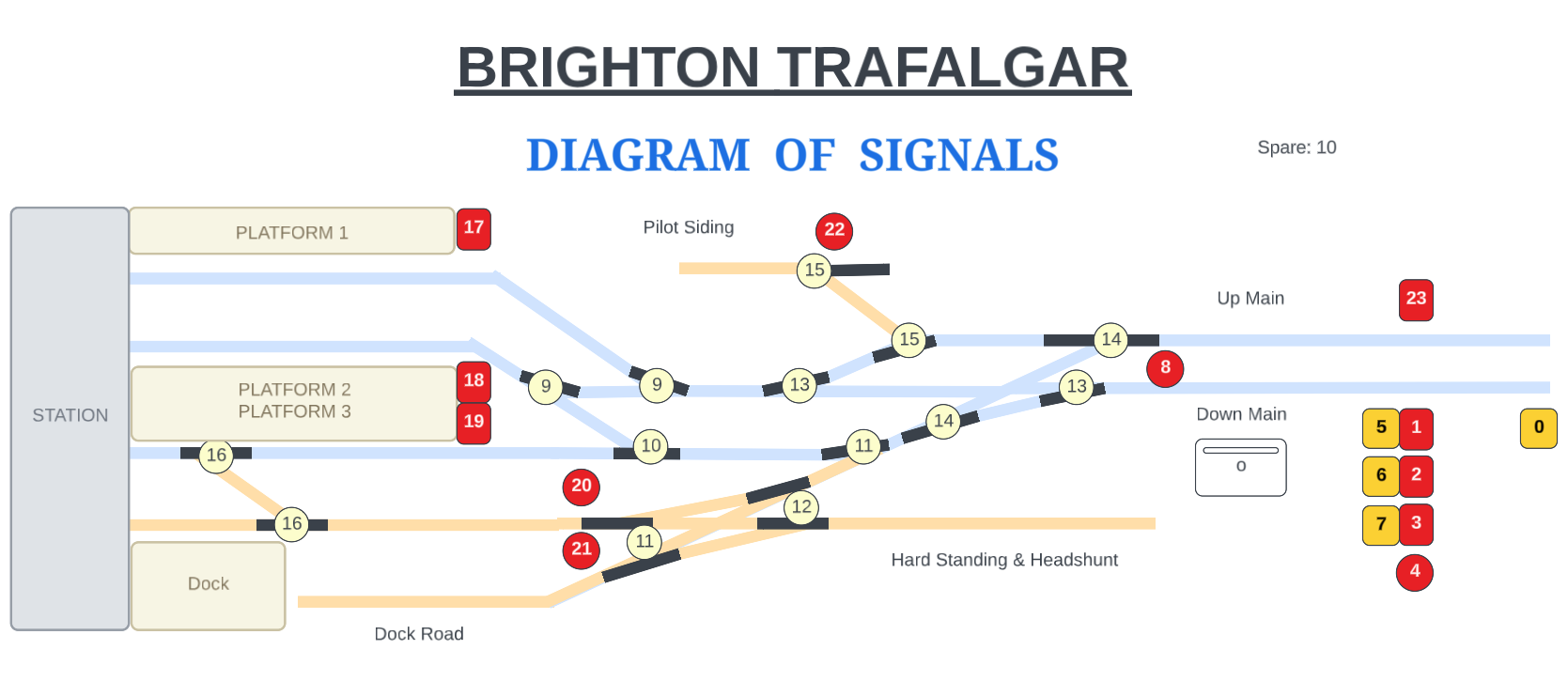
Each number on the diagram references a lever (switch) in the frame which is used to control all the points and signals on the layout.
There are a few small caveats to this layout which I will illustrate:
- Lever 0-7 and 23 will be represented by 3D printed spacers initially. They may end up being used to control an LED board on the fiddle yard for the benefit of a FY operator as an interim step, or until such time that I have constructed the extension board to model the approach to the station where these signals can be mounted properly.
- Lever 16 is shown as the crossover between P3 and the runaround and this is what it will do in reality, but in theory is just a ‘ground frame release’ for a ground frame at this location.
- I’m not sure that I need both the shunt signals marked 20/21 – I think I can scoot up 20 to be closer to the platform line and have a single shunt signal to protect both entrances to the double-slip, since both 20/21 can be passed at danger with points normal in order to access the headshunt, and both reference the same point lever reversed. I would appreciate any kind of confirmation on that.
Facing Point Locks
An extract on FPLs is below:
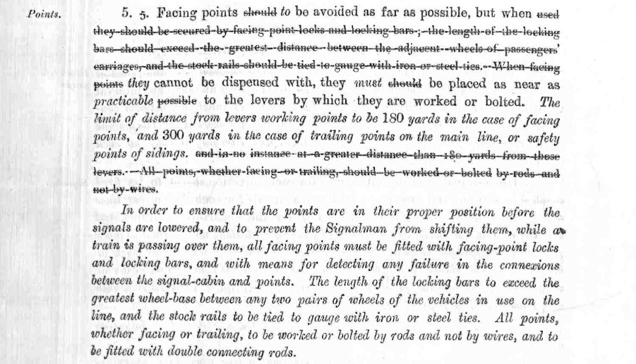
For the purposes of the Brighton Trafalgar layout, this means that any turnouts which face the direction of travel for a passenger train must have an additional lever on them which ‘locks’ the main lever in place.
I have chosen to omit facing point lock levers on my layout, though they are essential to the safe operation of a real railway, realistically in my case it simply means doubling-up every point lever in the frame with an second lever that provides a toggle for the first.
Point Levers
In addition to the DCC Concepts motors, I have also gone with their S-Lever frame solution. It is expensive, but one which allows me to move forward.
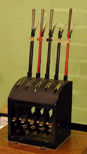
These levers have their momentary contacts wired to DB37 breakout boards in the lever frame, and the lever frame is connected to the layout board with standard DB37 serial cables. Two cables are required to carry all of the connections – one for the signals and turnouts on the throat board, and one for the as-yet unmodelled station home gantry.
Electronic Interlocking
Unfortunately the use of Cobalt Levers precludes mechanical interlocking, but a form of electronic interlocking a-la Bodmin could be implemented at some future point.

You must be logged in to post a comment.