In order for levers in a signal box to change the position of turnouts in the era before point motors, there was a need for a mechanical linkage. These are rods which snake their way out of the signal box across the permanent way to connect tie bars and locks with those polished levers. These rods need to be guided in their route from box to point, and this is done through a series of cranks and rollers.
Point Rods
The first thing to do was establish the location of the signal box on the layout, and then to plot the route of all of the rods to every turnout that needs to be moved.
Point Rod Rollers
The rods have rollers every 8′ on straight sections and every 6′ on curves, and where there are parallel rods the rollers are grouped onto a stool consisting of a stand and axle, on which a number of rollers are mounted. Following the plotted lines, it was a simple process of establishing the number of rollers on each stool, and the number of stools thereof.
While stools are available from Wizard Models, it feels mad to pay for such small bits which can be easily produced at home on a 3D printer, so I went about drafting a design.
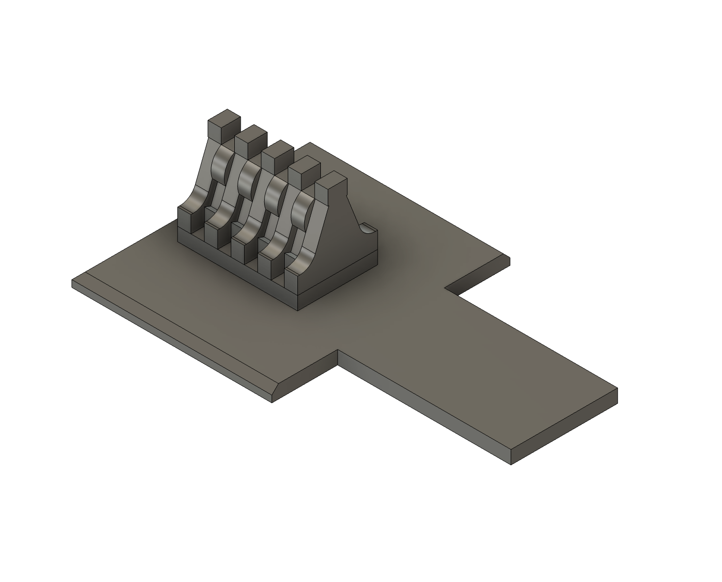
Prototype Roller Stool

The prototype roller stool as shown above matches drawings of standard point roller stools available from contemporary magazines (the specific mag/issue eludes me now) and would be perfect for a large scale reproduction, but does not read very well at small scale, so a much simplified equivalent was designed:
2nd Prototype Roller Stool

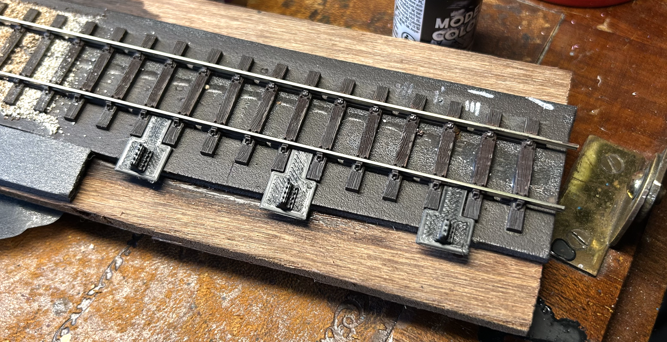
A quick mock-up on my long-suffering test plank indicated that a 1.5x -scale print would work fine:

Production Roller Stool
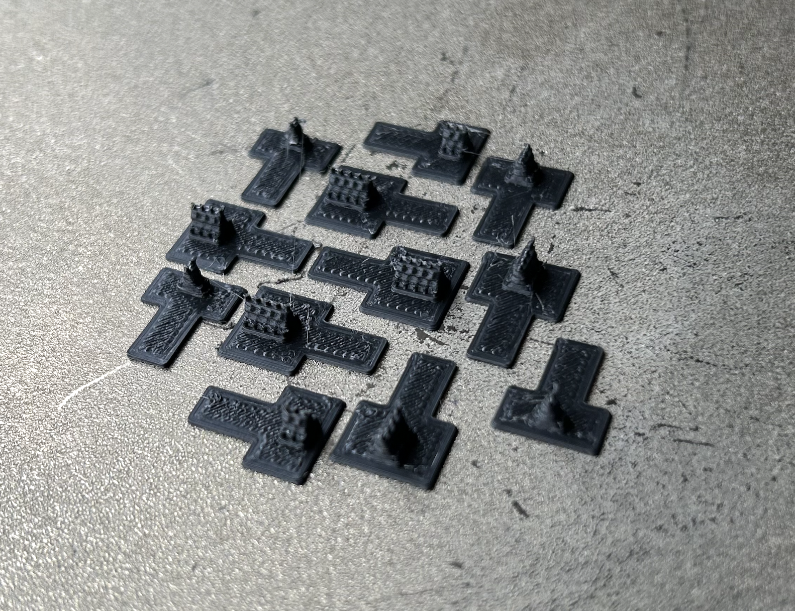
Compared to buying commericial whitemetal castings, these are easy to use (requiring no fettling or filing) and significantly cheaper at approximately £1 per 360 stools – or about 50p for my entire layout!
The Thingiverse link is here: https://www.thingiverse.com/thing:6865049
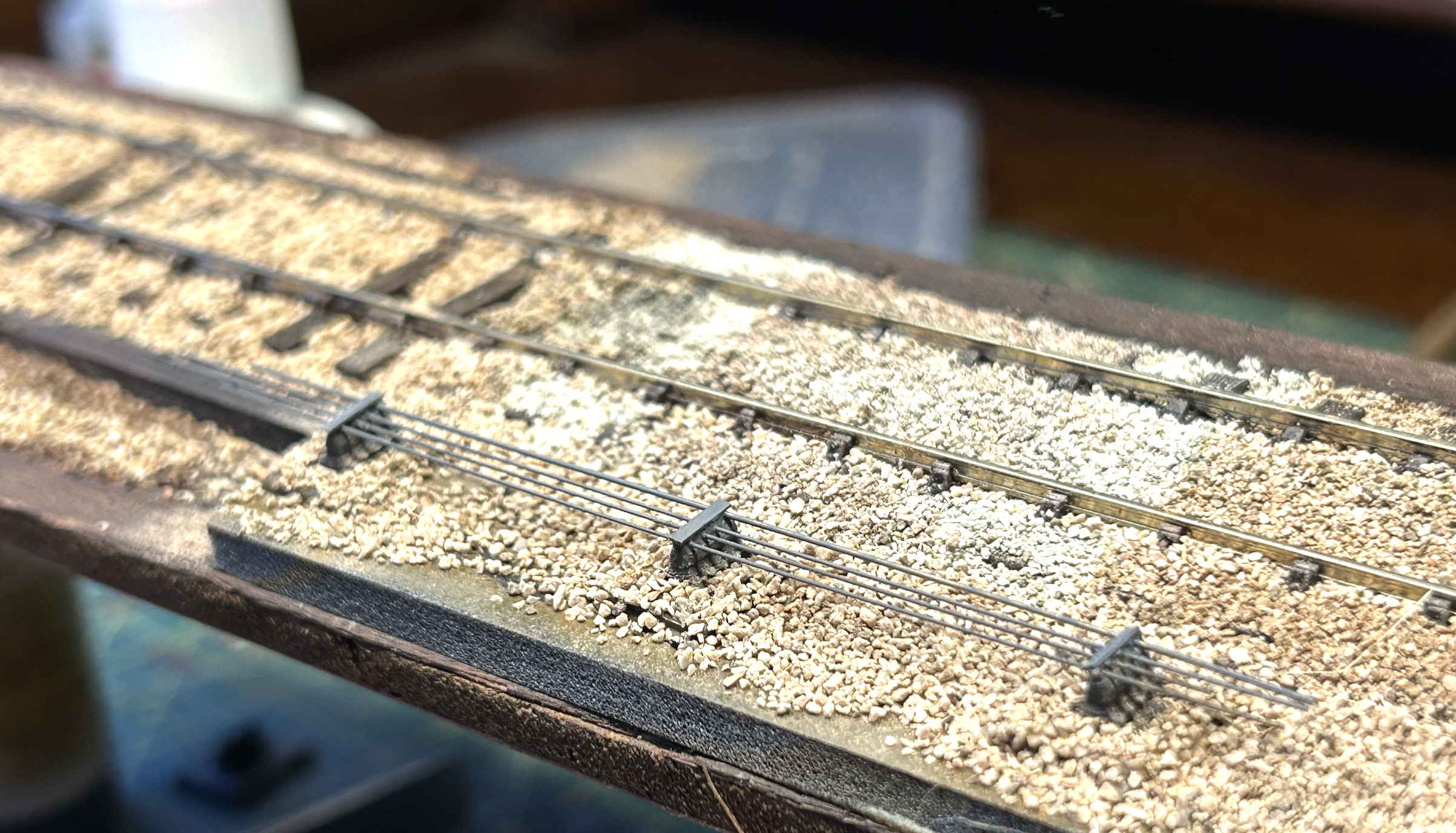
Laying the rollers out at approximately the correct spacing on the layout has reassured me that this approach is a good one:
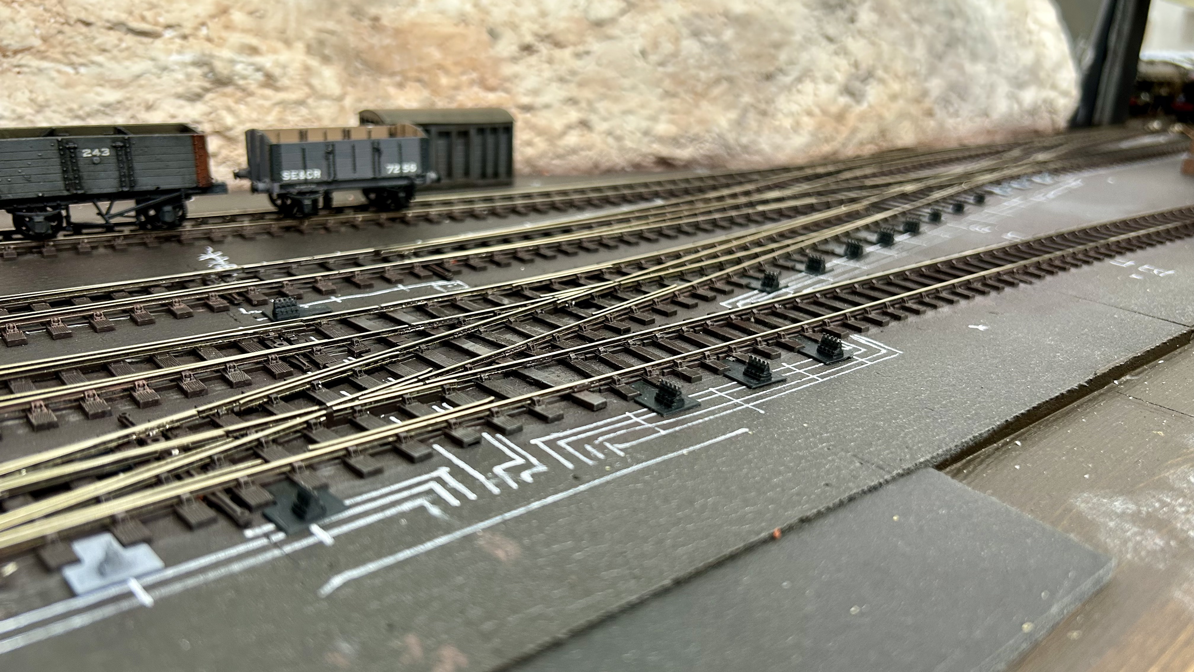
Laying the Rollers
Point rodding rollers need to be closer together than you might think, around six to eight feet, so I decided to standardise spacing them between every three sleepers or timbers. It was difficult to plan the whole rodding run effectively, because I printed stools with one, two, three or four rollers – so these needed to be placed in the correct order as rods terminated at turnout linkages.
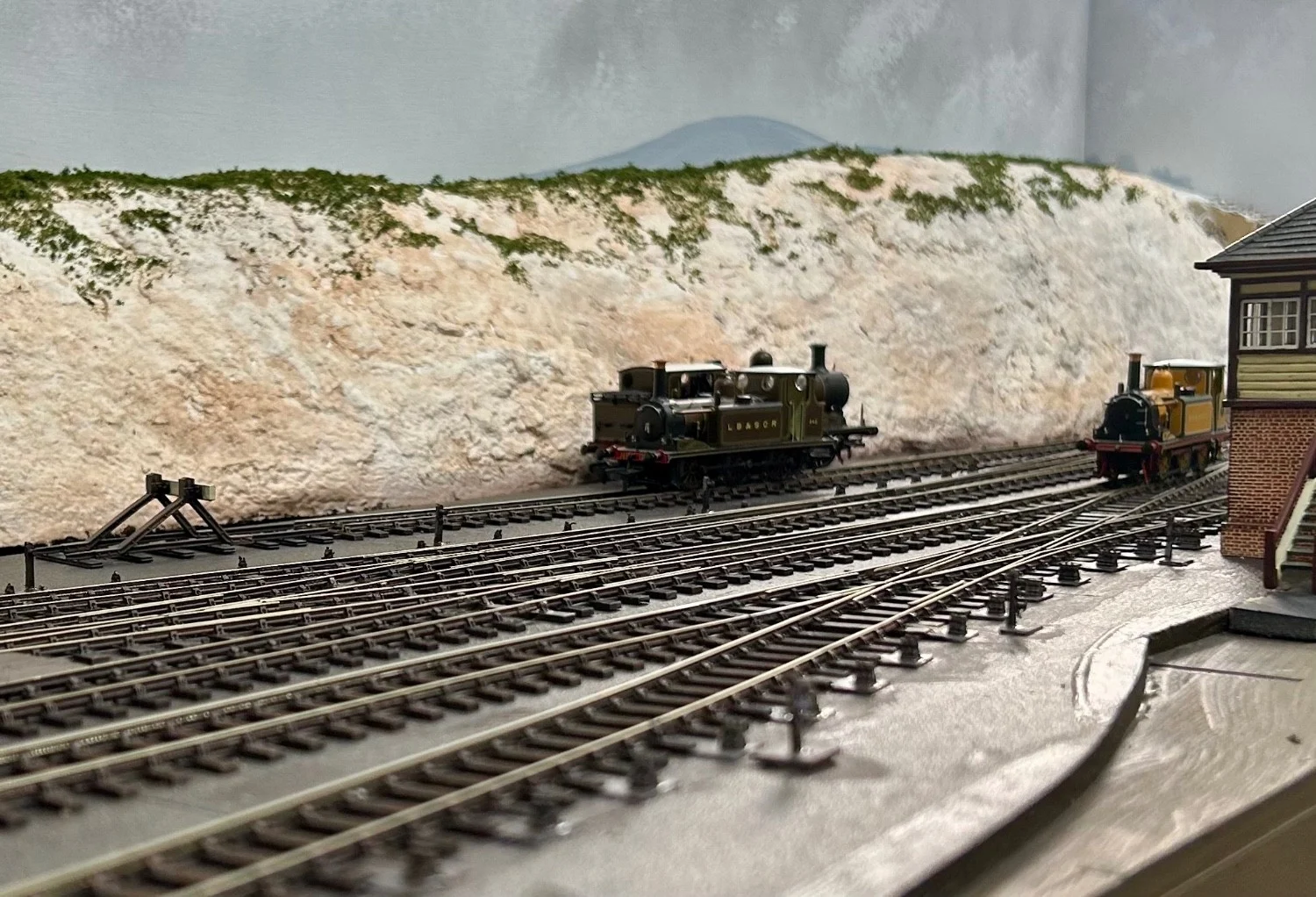
It may not be perfect, but I think I have a reasonable approximation!

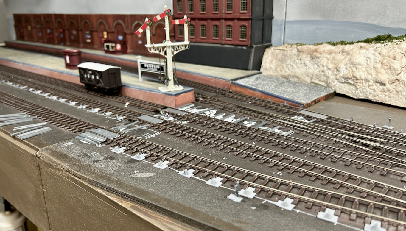
With a coat of German Camo Black-Brown, they are suitably blended into the overall scene. Soon, I will need to get on with ballasting to reintroduce some contrast and lift the overall brightness of the scene!


You must be logged in to post a comment.