Normally considered part of the station in layout builds, I feel the fact the trainshed is deliberately separate and distinct from the station building is enough to consider this a separate part of the scenery.
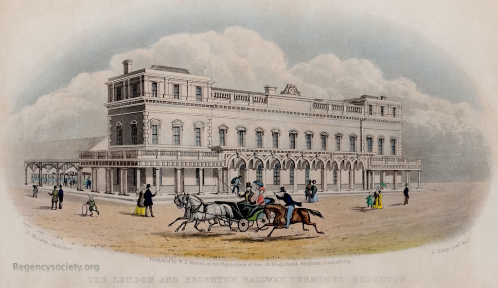
My original plan was to use a shortened version of the ‘new’ Brighton station trainshed walls as a backscene for the rear platform. I measured the centres of the the roof trusses using Google Earth, then used the following photo for dimensions of the arch detail:

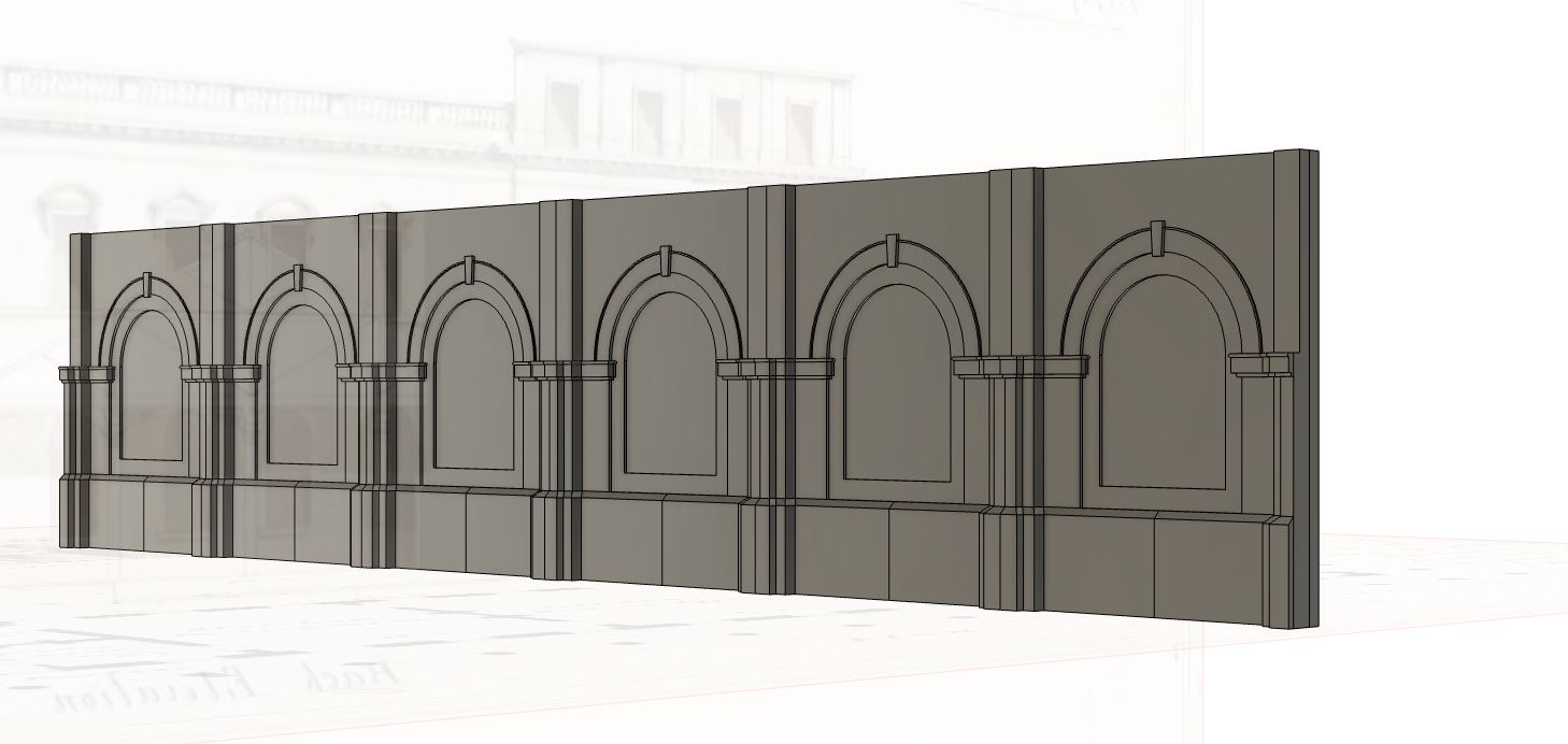
Using the column height from the station building plans, I was able to establish a potential height for the pilasters, and this resulted in the following 3D model:
Upon reflection however, I realised that this was probably the wrong choice – the pilasters represent the base of the roof arch which curves up to meet a straight line from the top of the wall – yielding a much higher roof than the earlier style I would like to model, shown below:

Based on the pillars on the trainshed-facing end of the covered way and the trusses resting upon them, the height of the crossmembers is 16′ over platform level. Note also the void in the rear wall, which was provisioned for a cab road. The wall isn’t part of the structural support of the roof, as it was originally built free-standing on more pillars:
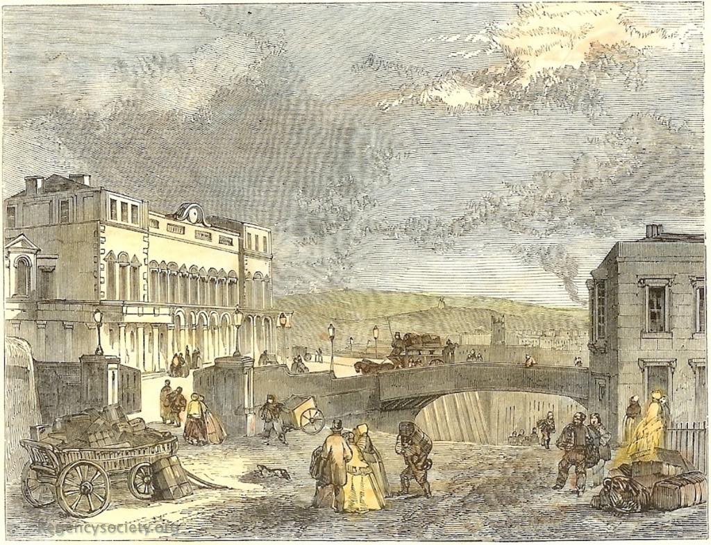
A slightly later 1854 engraving of the same shows the addition of a two storey extension north, a boundary wall and the bridge over Trafalgar Road infront of the forecourt. Presumably the wall behind the trainshed was built as what became ‘Terminus Road’ was laid out.
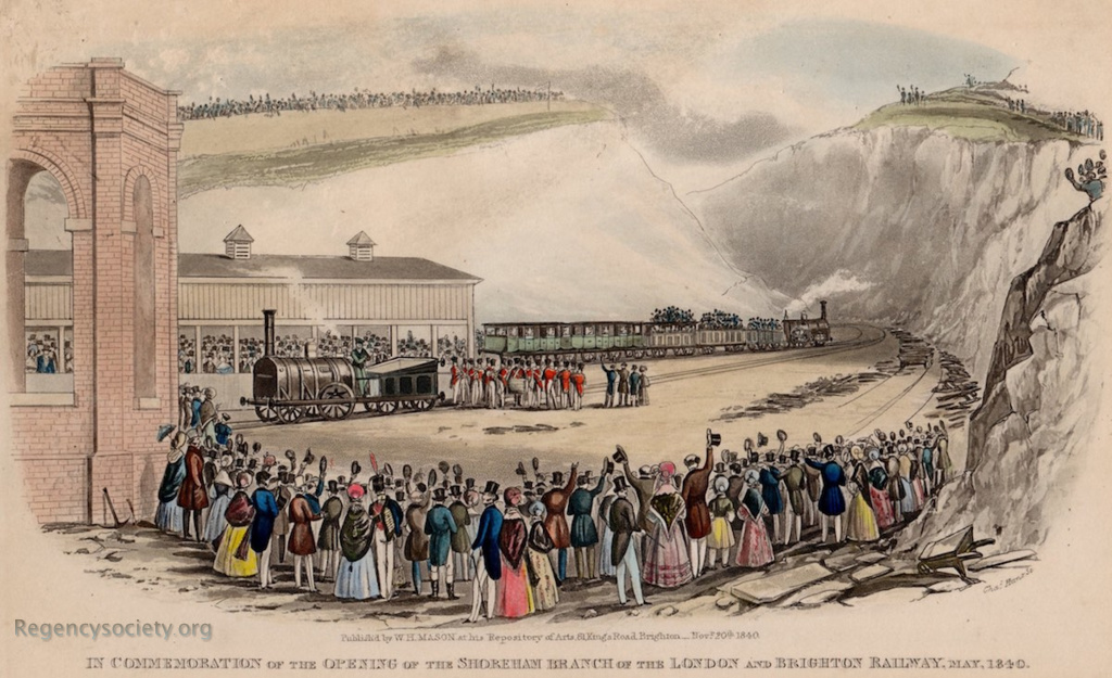
Though not totally relevant to this discussion, an earlier 1840 engraving shows the same trainshed under consideration looking more like a wooden carriage shed with cupola vents. Note that in this engraving, only the Shoreham/North side of the station is in use:
The rear elevation of the 1840 Mocatta drawing shows the pillars supporting the outer edge of the covered walkway, and the outline of the roof trusses and supports:
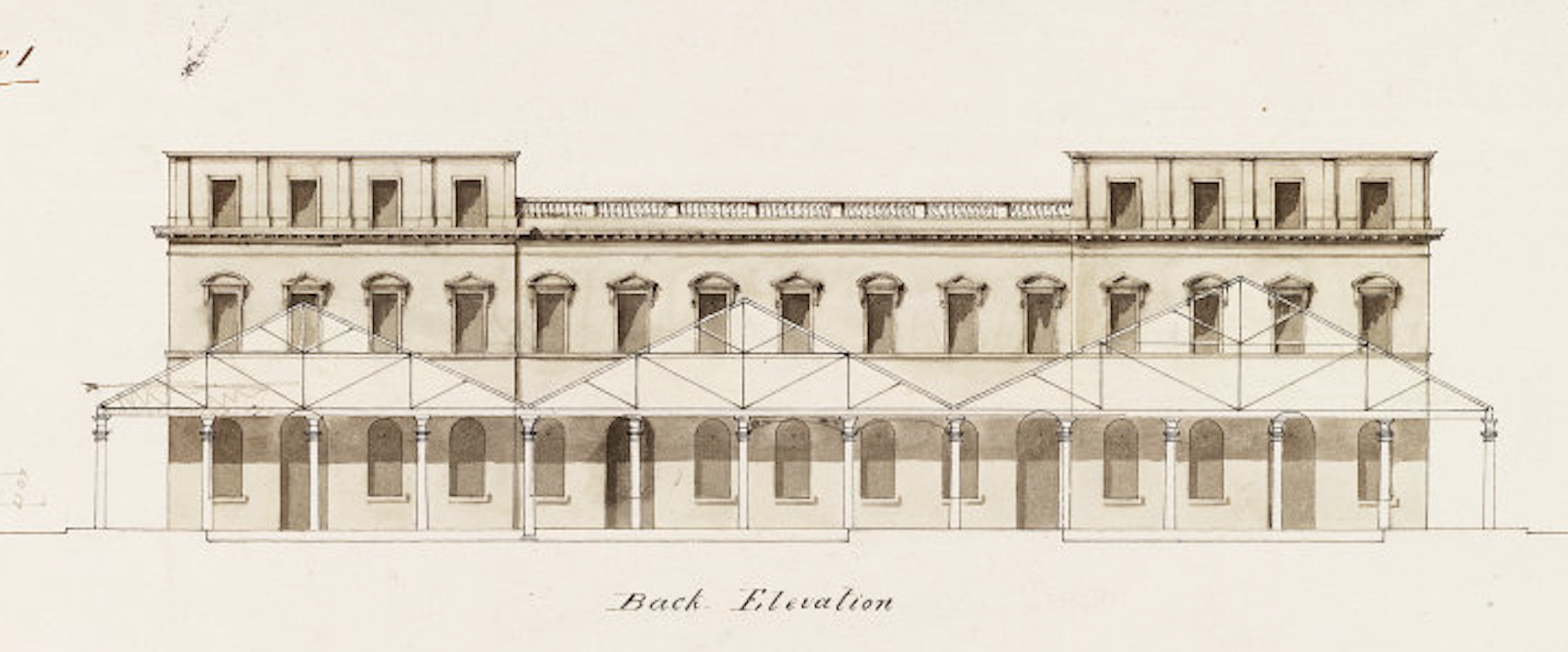
Note the asymmetry with the right hand canopy 12′ wider and the apex rising above the line of the windows and an asymmetric pitch, and that the support columns of the covered way do not correspond to the trussing of the roof. By referring to the Earp engraving above, it seems that the centres of the pillars along the length of the platform were more widely spaced than those of the covered way.
Overall Roof
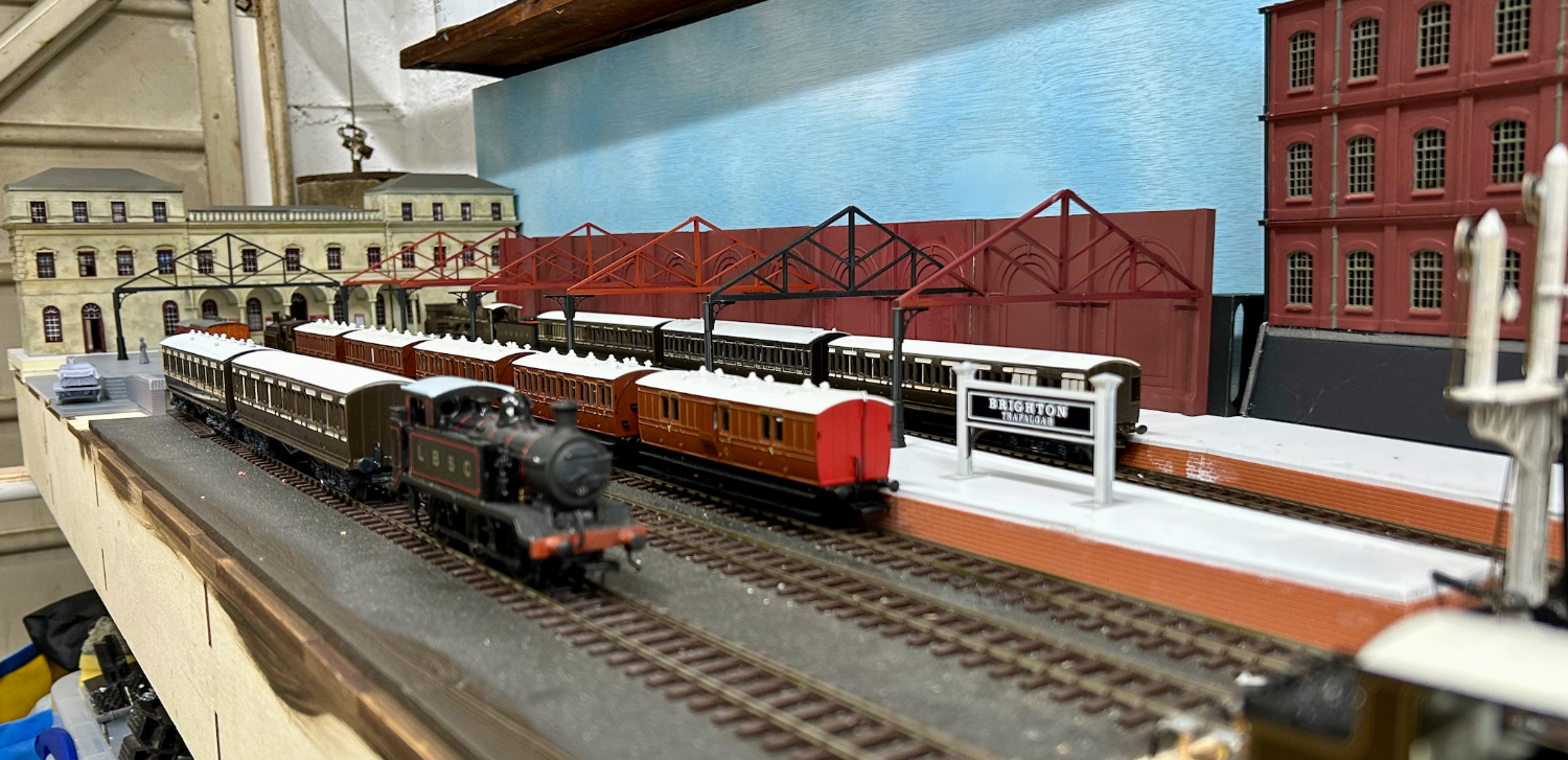
I decided to lift the pattern of the overall roof directly from the 1840 Mocatta design for the building, despite the slightly different use in mine (the original was free-standing, while mine will integrate with the trainshed wall), and freelanced the columns based on those outside the station holding up the exterior canopy. A quick print resulted in a nice outline of the space occupied by the trainshed.
Trainshed Wall
I felt as though the trainshed wall design while not strictly accurate for this use was good enough, and so I proceeded to print and assemble them 11 of them, using 45mm spacers behind to provide a greater contact area for adhesive and to bring the wall a standard distance away from the backscene. I used the CAD software to slice and extrude additional pillar halves to bulk out the ends of the trainshed wall when viewed side on.

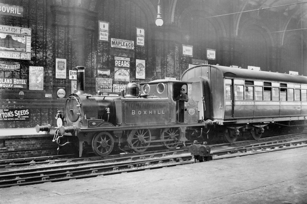
I was keen to try to replicate the following shot of Boxhill:
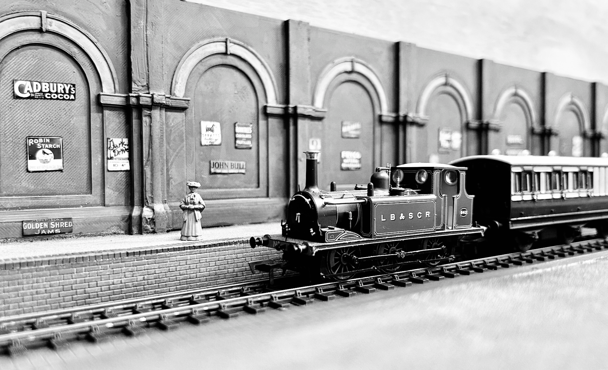
With a platform kiosk and station office in situ, it in my own opinion, starting to look quite nice:

There are still a number of details to add at this stage – more advertising signs, ballast, ground signals, etc. but I feel as though this is a reasonable stopping point to move onto other areas of the layout which need focus.


You must be logged in to post a comment.