Preamble
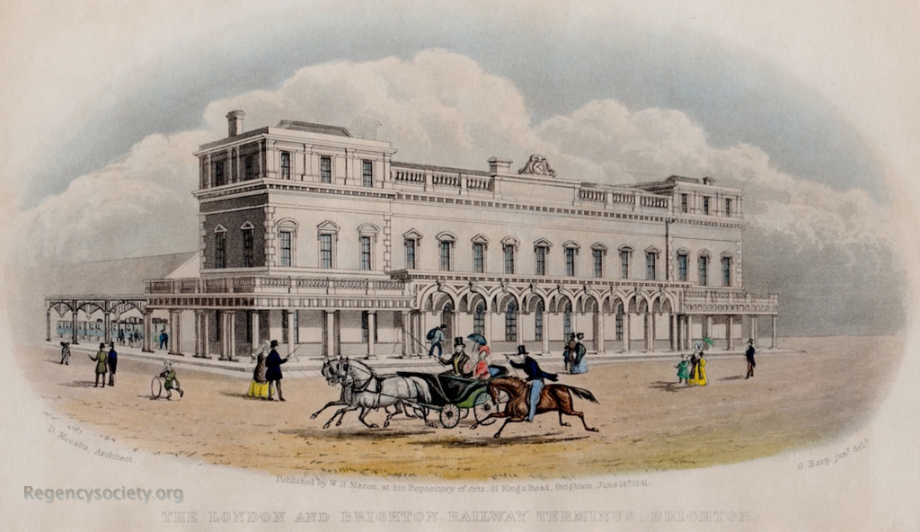
The largest and most significant structure on my layout is the station building which caps one end. The inspiration for my layout draws very heavily upon the original Brighton station before the 1894 rebuild, and so it was natural to look to that for design cues. I was very pleased to find that the Registered Institude of British Architects have made available series of drawings by David Mocatta for the original building.
It was on these architectural drawings that I formed the basis of my initial plan to copy the footprint of the building and the relative widths of the station platforms while freelancing the details, but I soon realised that the building could be represented almost verbatim on my layout and still fit within the available space.
The Real Building
In plan, the building is mirrored down the centre – the north side being dedicated to Shoreham, and the south side to London. The ground floor of each half has a booking office, ladies and gents waiting rooms, a parcels office and a staircase. The upper floor consists of offices, with the central area hosting a board room and secretary’s room.
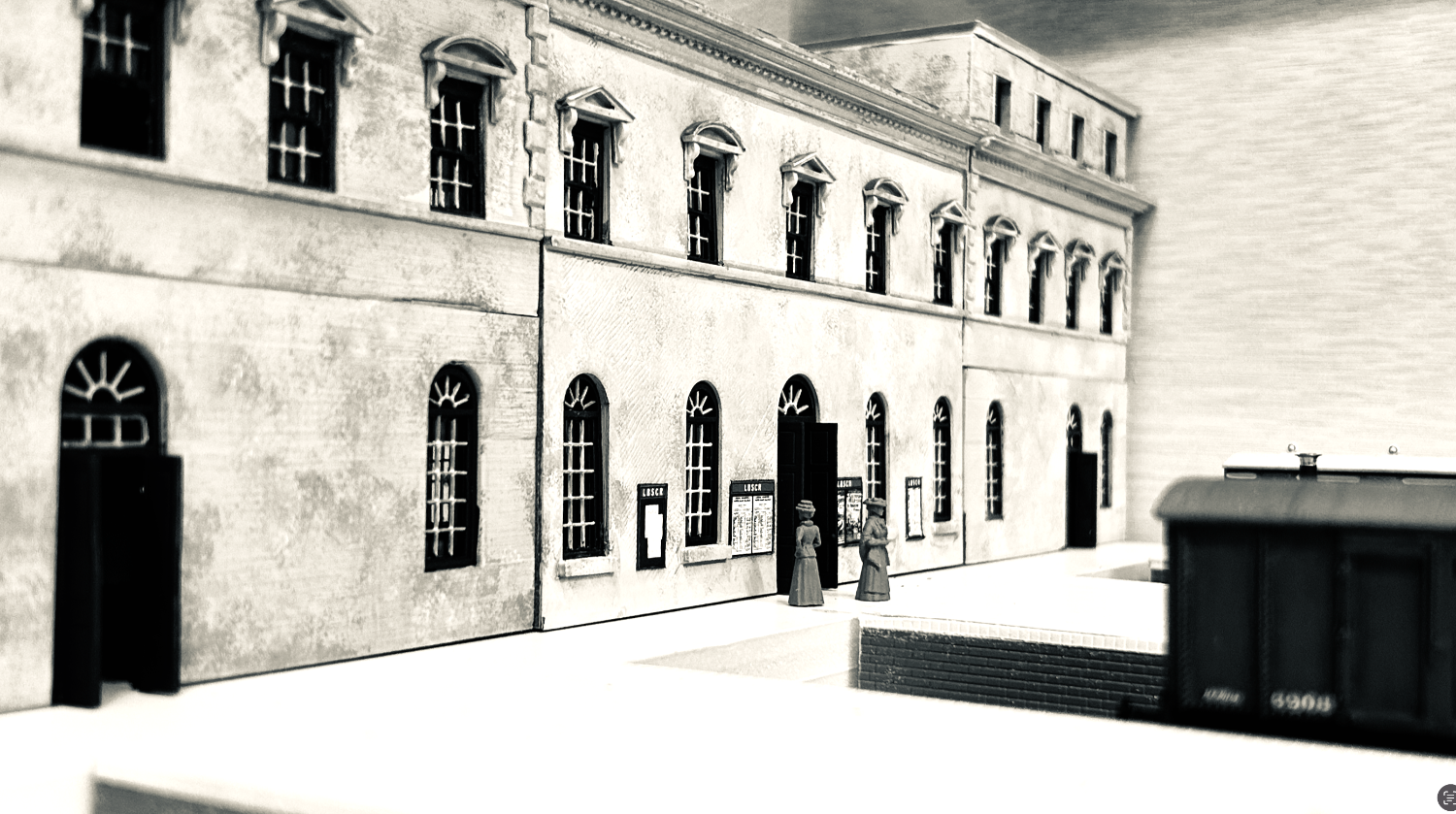
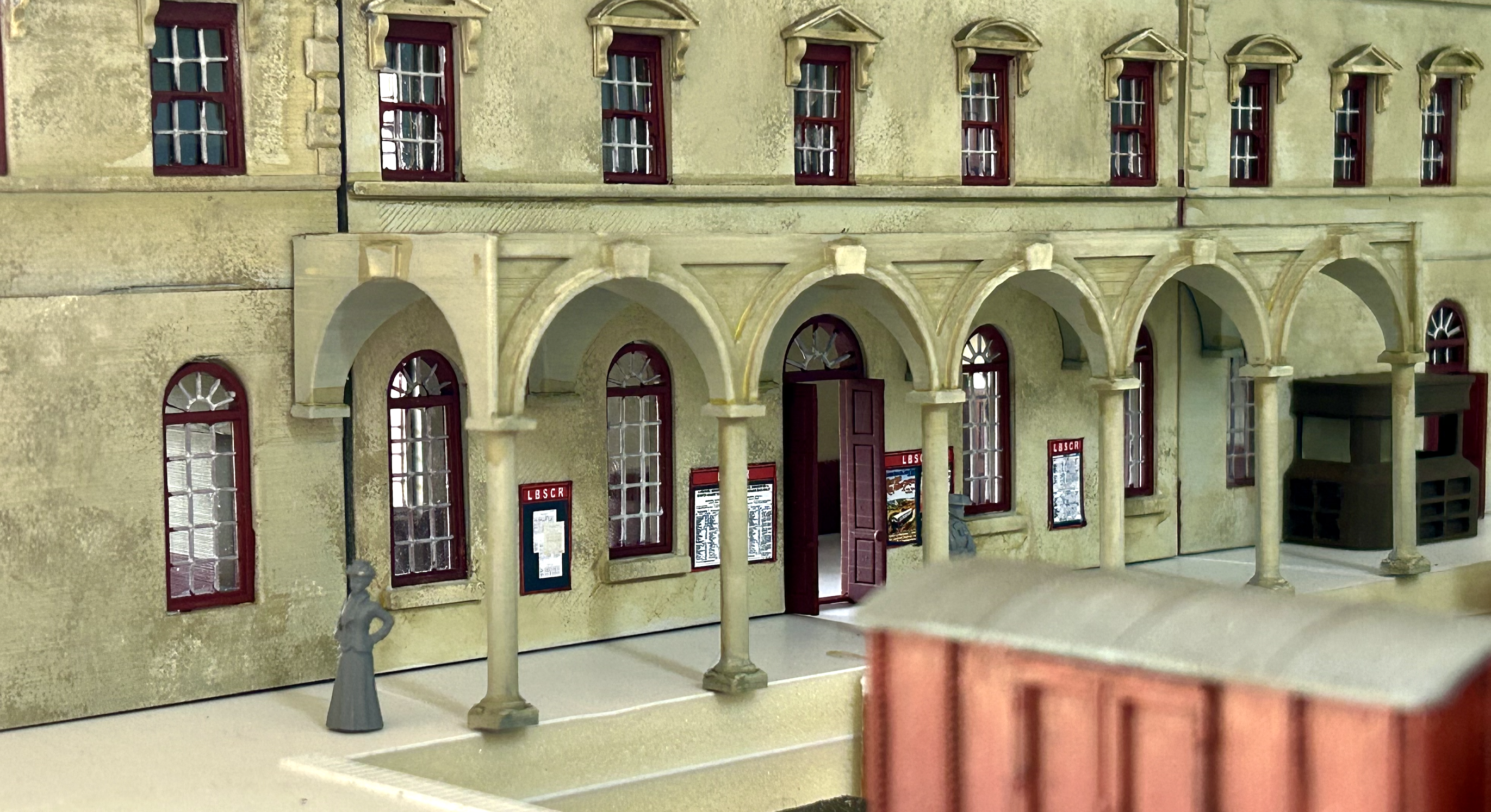
One of the most distinctive aspects of the station as-built was the wraparound covered way, gilded with balustrades, vaulted under the road entrance and supported by tuscan columns. This covered way separates the trainshed from the station building, and delineates a tiny platform-end concourse.
Mock Up
In order to get a feel for the size and space of the building, I created a paper mock-up using a 4mm/ft print of the plans and taped this to some scrap foamcore carcasses.
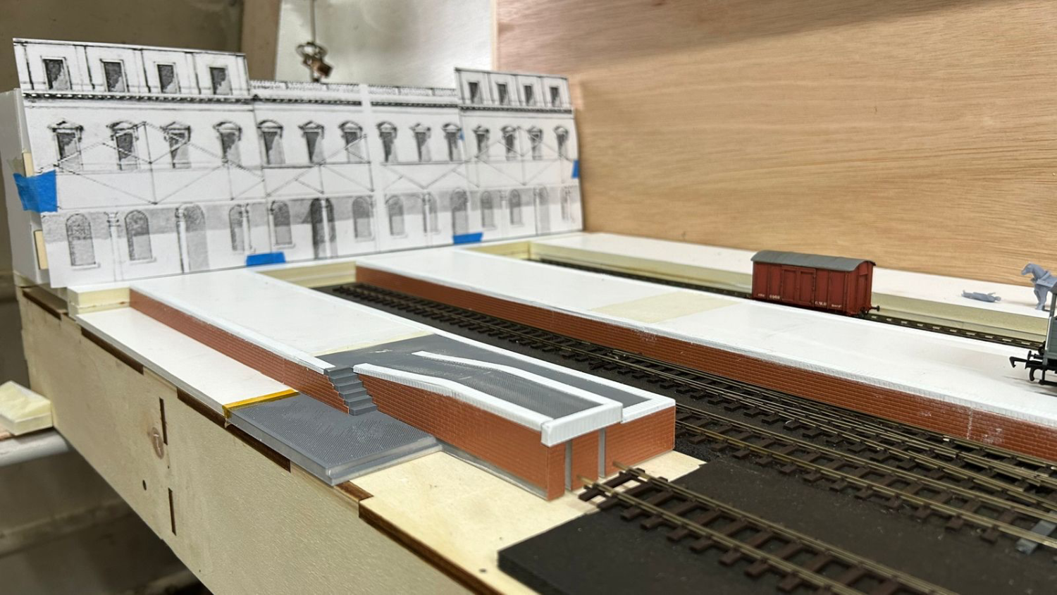
This exercise was very useful, for I realised that I would need to reduce the depth of the real station building by about a third and overall scale the structure down by about 10% – both of which to clear the up-and-over door to my garage.

3D Printing Setup
Hardware
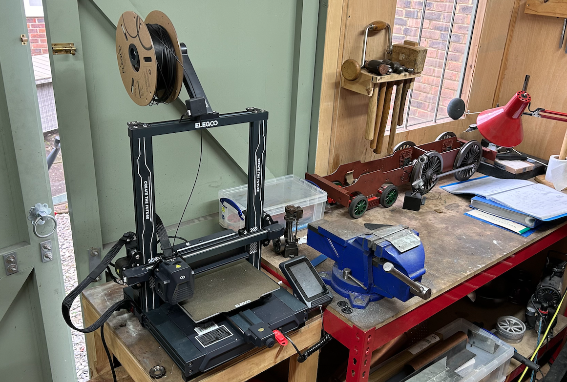
That proven (with a long interval) I needed to get started. My original plan was to use styrene, and then with so much repetition of features my thoughts turned first to Cricut or Laser Cutting, and then to 3D printing. I recently purchased an Elegoo Neptune 4 Pro, which is a very simple but high quality filament printer, and had reasonable success in printing other people’s designs and very simple components for myself. I decided to give it a go to model this building in 3D and print it off using the bog standard Elegoo PLA filament.
SOFTWARE
Fusion360 is my tool of choice for anything more complex than a couple of primitive shapes (for which I find Trimble Sketchup more suited). There are many excellent tutorials for F360 and it is free for non-commercial use, so I won’t make a pig’s ear here by trying to explain what I’ve done inside the tool itself – I should really emphasise however that I am a beginner, and there was nothing difficult about this at all and I would urge anyone who is remotely interested to have a go.
MODELLING THE BUILDING
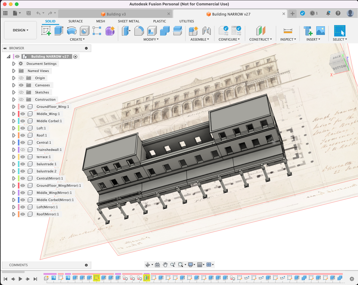
It was a relatively simple process to import the blueprints from RIBA into the software, trace them and then extrude into the third dimension. I did this for each of the floors of the wing, then set about sketching the window voids and ‘cutting’ them out of the modelling. Decorative features such as corbelling were done in a similar manner – by extruding along one dimension and then repeating as a pattern around a path drawn in another.

A simple way to manage the construction is to make each piece a ‘component’, which can be keyed off of each other:
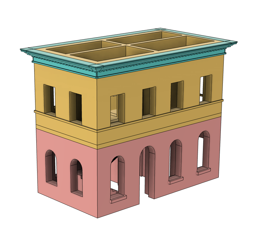
The biggest challenge was to ensure that features matched up with each other, and it was to my demerit that I did not discover a cross-section drawing with more thoroughly detailed the internal doors and staircases until after I had finished the principle modelling which made that more difficult than it needed to be.
Luckily, Fusion360 allows you to ‘time travel’ back and forward so you can go back and change or reorder actions you’ve taken!
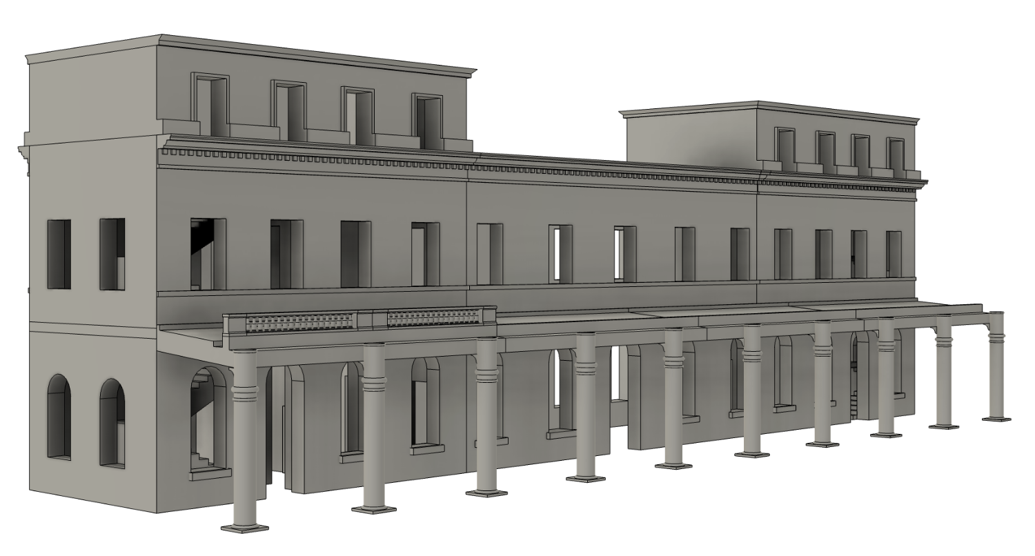
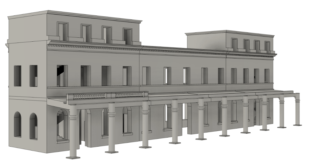
The 90% finished model of the station carcass gives a good impression of what this station would look like in the flesh
Printing
The process of printing was iterative, with each floor of the wings, the front and back of the central section, the corbelling and roof, pillars and covered way all being printed over the course of a week or so.
The first part I printed was the ground floor of the south wing, shown here with some posed Andrew Stadden figures:
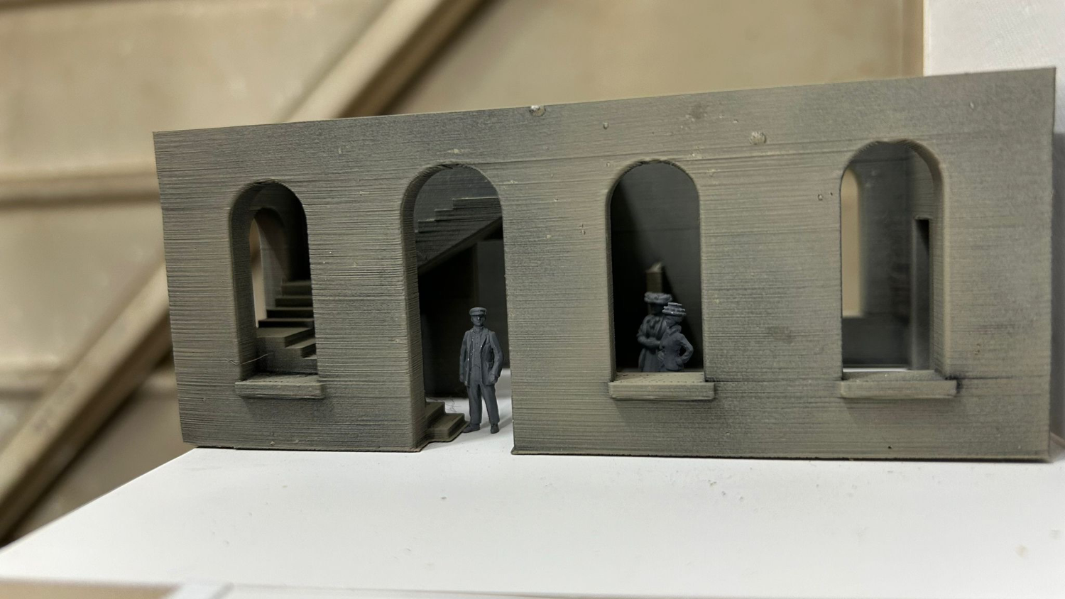

Though the covered walkway is printed, it requires permanent fixing to be held in place and so is not fitted. The next step on this journey will be to add details – internal floors, window and door inserts and hipped roofs.
Details
Having printed the main carcass of the station building, I naturally moved on to other things, but with a little time off work looming I realised that I had a fair run at finishing the building.
Many people may be under the impression that for 3D printing it’s a case of clicking a few buttons and parts fly out ready to be assembled, but hopefully my description so far is putting paid to this. There was a long process of iteration with design of details – both plain and sash windows, fanlights of multiple sizes, double- and triple-panelled doors, etc.
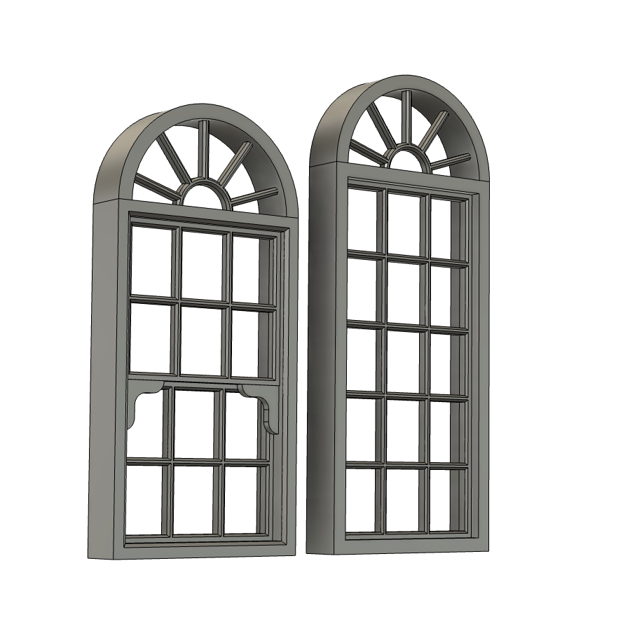
A test print showed that a window bar thickness of 0.5mm could be printed in resin and retain structural rigidity as long as it was washed and cured quickly (too long and the weight of the uncured resin would start to bow the thin and still-flexible bars) – so this was used across the board.
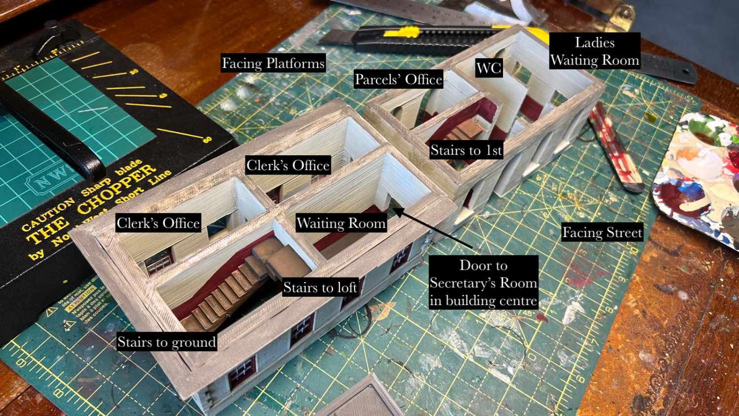
Interiors
When painting the interiors I realised that the compression of the building in thickness has meant some of the rooms end up being rather narrow – but that is a compromise I’m willing to make in order to fit the building into the space I have available.
Lintels
I also modelled the distinctive alternating curved and triangular lintels used on the building, with cornices that span the window void. These were glued in place while the windows were a press fit.
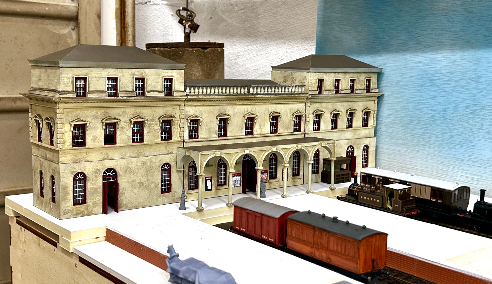
Vaulted Arcade
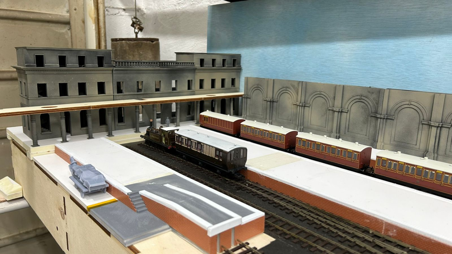
Apart from the collonaded covered walkway, one of the last pieces to be designed and printed for the building was the vaulted arcade that graced the street-facing entrance to the booking hall. I have temporarily sited it on the platform-side as a temporary stand-in for the aforementioned covered way:
The method of construction for this particular piece was fairly straightforward – a superimposed a rectangle over the underlying central hall drawing to outline the arcade, then draw a series of features concentric to the underlying windows (thankfully I had spaced them regularly otherwise this wouldn’t have worked at all), followed by a simple series of extrusions to provide the features shown.
For a building like this there are always infinitely more details to add – more posters, internal room detail, gutters and drainpipes and general clutter – but at this point I considered the station building sufficiently complete to place on the layout.
Placing the Building
The following diagram shows the location of the building in profile with the end of the baseboard. While I wouldn’t typically be interested in modelling a forecourt, the angle of the up-and-over door precludes pushing the station building back any further. Indeed, experiments showed that even with a flat against the end of the baseboard I would not increase any of the platform capacities in a meaningful sense.
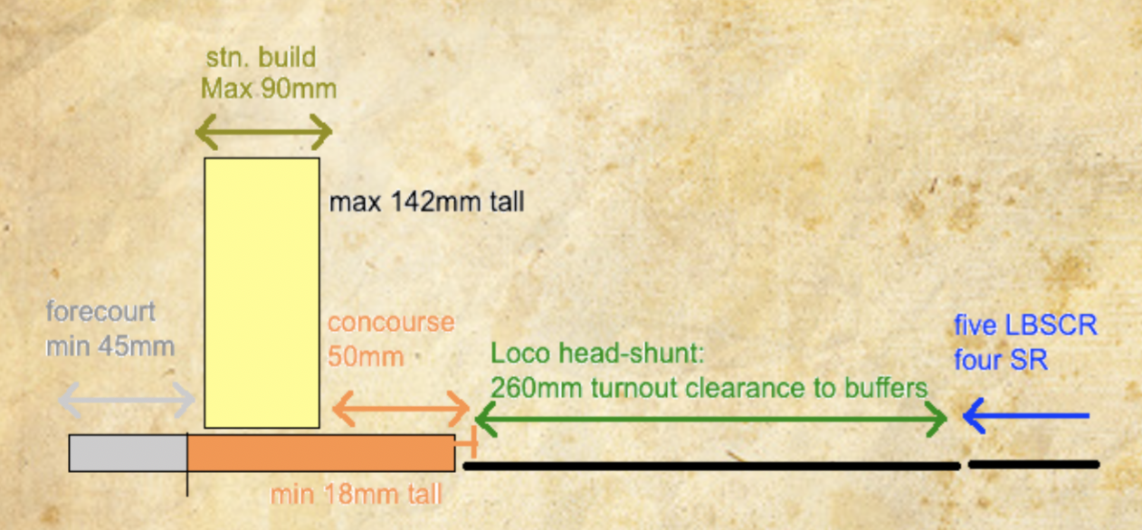
As you can see, there is no station concourse as would be provided at other larger stations at this early date, which suits me well as it allows the longest possible platform roads while still keeping the station building in the correct position to clear the doors.

You must be logged in to post a comment.