Background
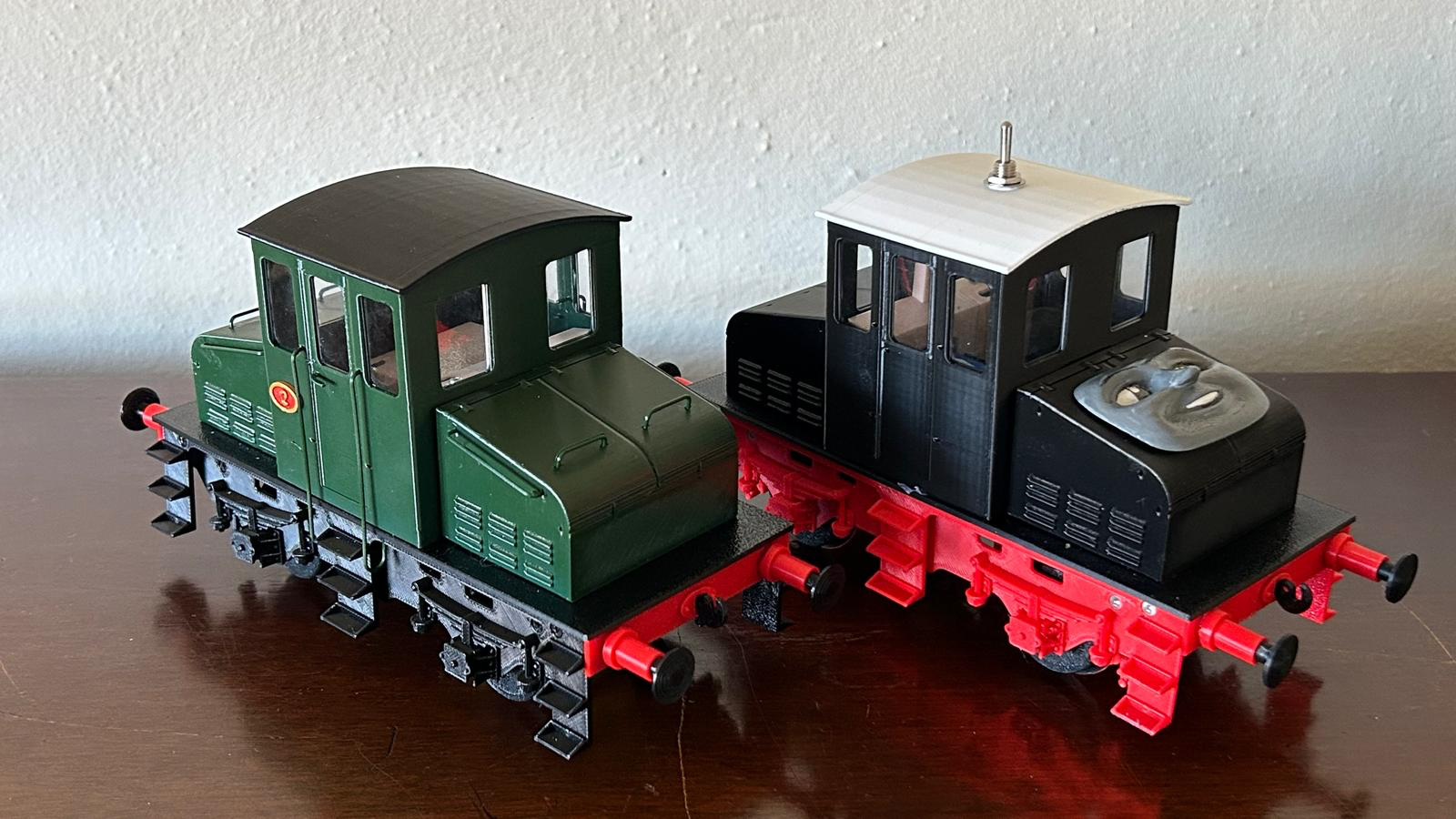
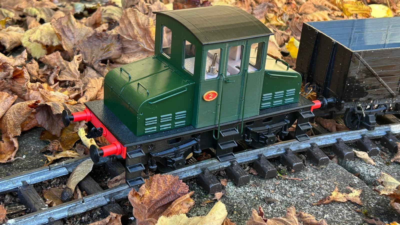
The LYR Battery Electric by Mr. P. Davis was my first ever Gauge 1 print, done on a cheap resin printer with no idea at all how it would work.
The size and scale impressed me, but I quickly moved on to other projects and this original effort sat forlorn and unfinished until in around Autumn 2025 I decided to wrap it up and make it a train to go ‘around the Christmas tree’ in American-style.
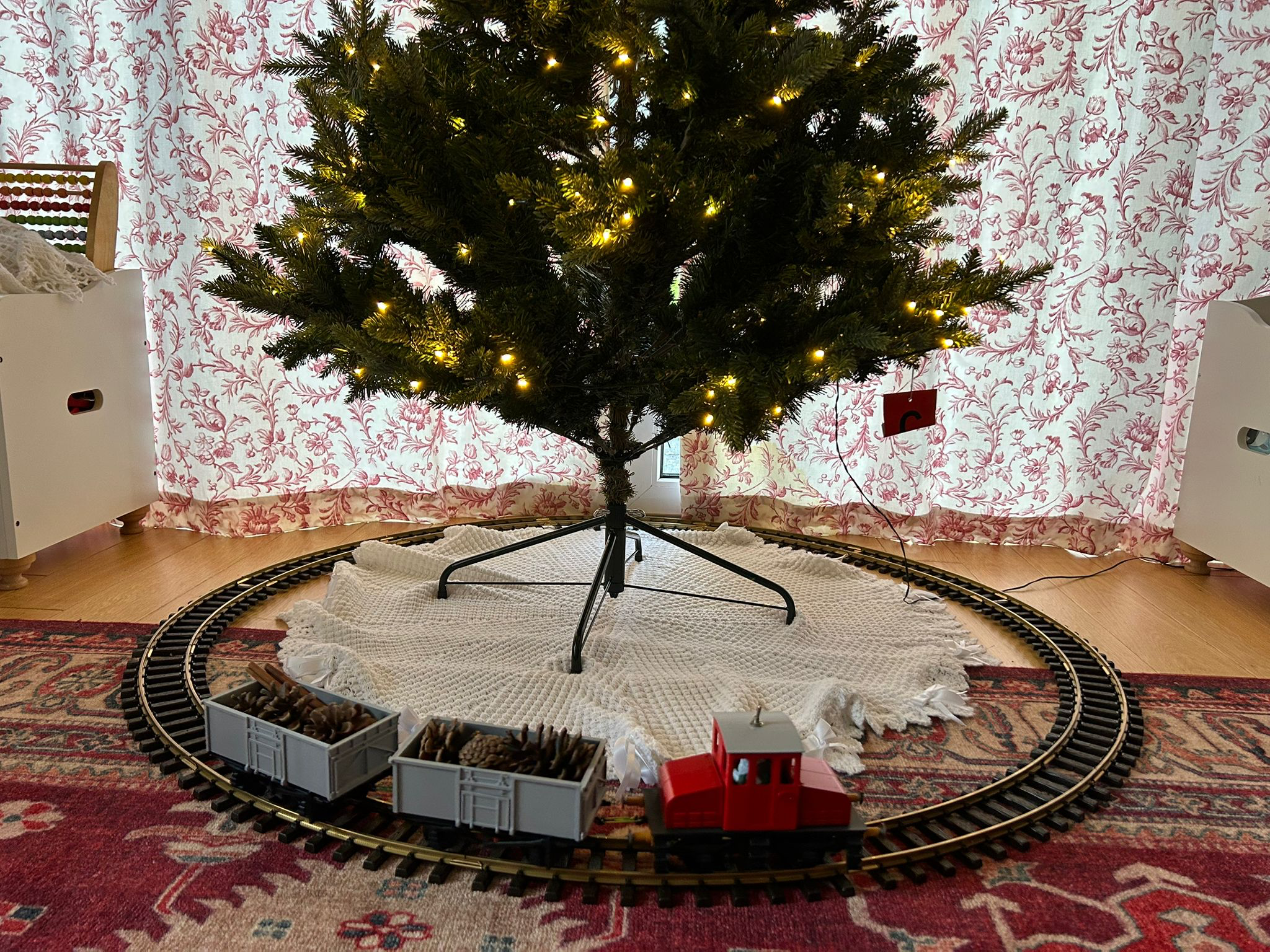
At this point I had no frame of reference or understanding of remote control, electronics, motors, batteries, etc. – and so I installed one (of the two recommended) motors and some AA batteries with a DPST switch on the roof – it was woefully underpowered and could barely pull a pair of mineral wagons around the tree and at a very slow pace indeed.
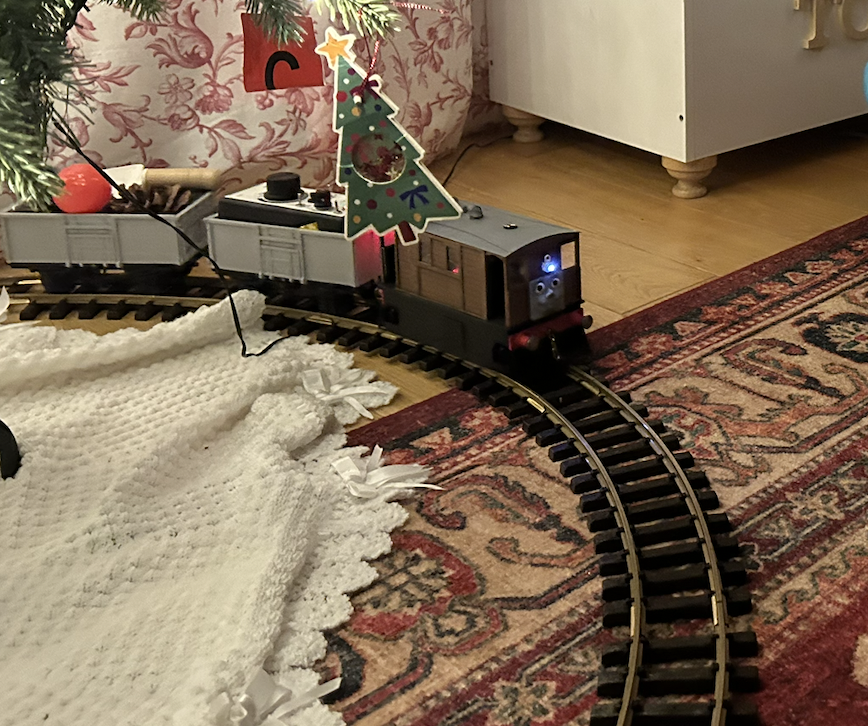
After the first weekend of rather desultory running, it was replaced by an LNER J70 / “Toby the Tram Engine” that I had built in the meantime.
Reworking
I have started printing up track and wagons to offer out as Christmas gifts to the children of neighbours and friends, after a few showed interest at my home beyond usual politeness.
Though the LYR Pug is an obvious choice for an aficionado, I wanted a known-good locomotive that I could experiment with, since the Pug is designed around some quite specific internal electronics (namely a Hornby HM7000 bluetooth DCC chip, 12v booster and so on).
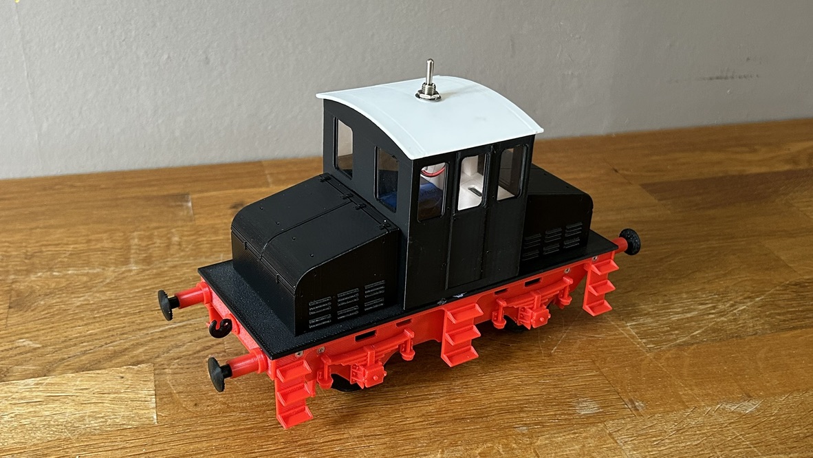
I decided that re-working the LYR Battery Electric No. 2 would be a good opportunity to learn more about RC and electronics in general, so inspired by the Pug I modified and created new parts to fit a standard cheap yellow geared motor, 18650 battery and USB charger (inspired by both the Greenly starter and LYR Pug), with a hope to fit a remote control system in due course.
New Inner Chassis
The first major step was to build out an inner chassis to support the wheel sets, since the unlike the original design which has a convention wheel set driven by gears, the yellow geared motor has bolt-on stub-axles.
Dummy axle box alignment
With a completely removable motor block the axle boxes of the loco become non-functional, so the first job was to design up some locating pins for them – a simple top-hat shape:
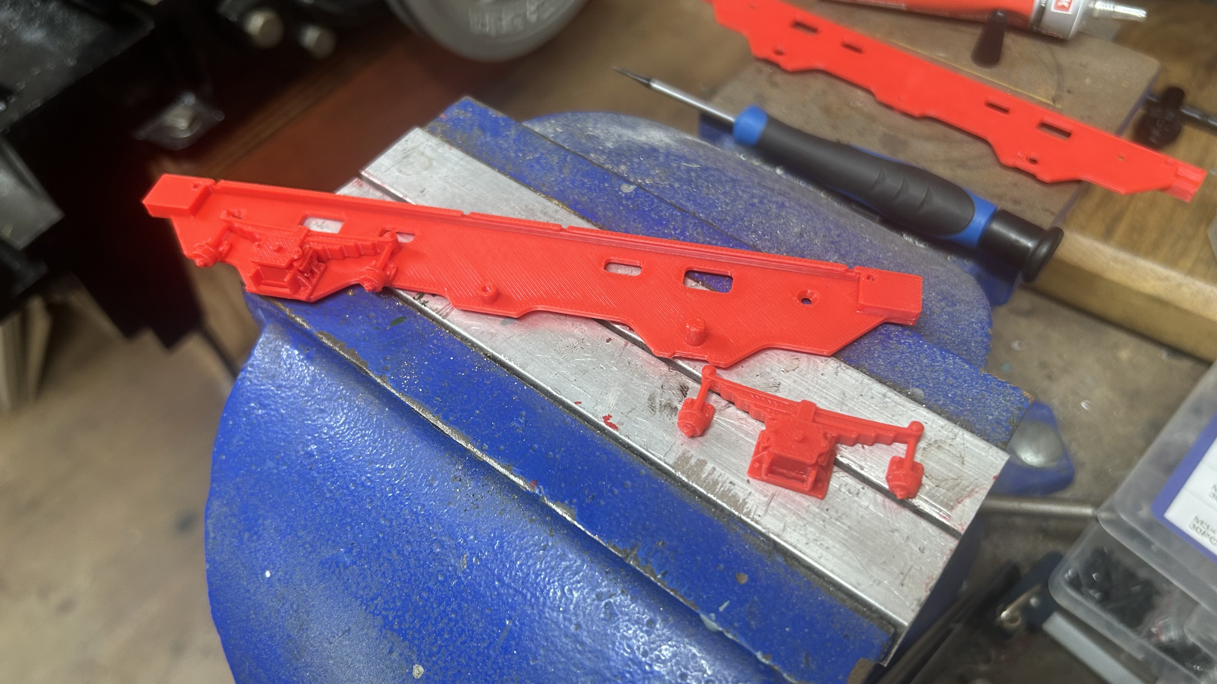
Shown above, these push through the axle holes and locate the axle boxes around the correct centreline.
Motor and idler blocks
Motor block
Both blocks are simple clamshell designs which aligns and captures either the motor and driven axle, or the idler axle. I re-used the cab floor fixing holes as a way to secure the block to the body, using M2 screws.
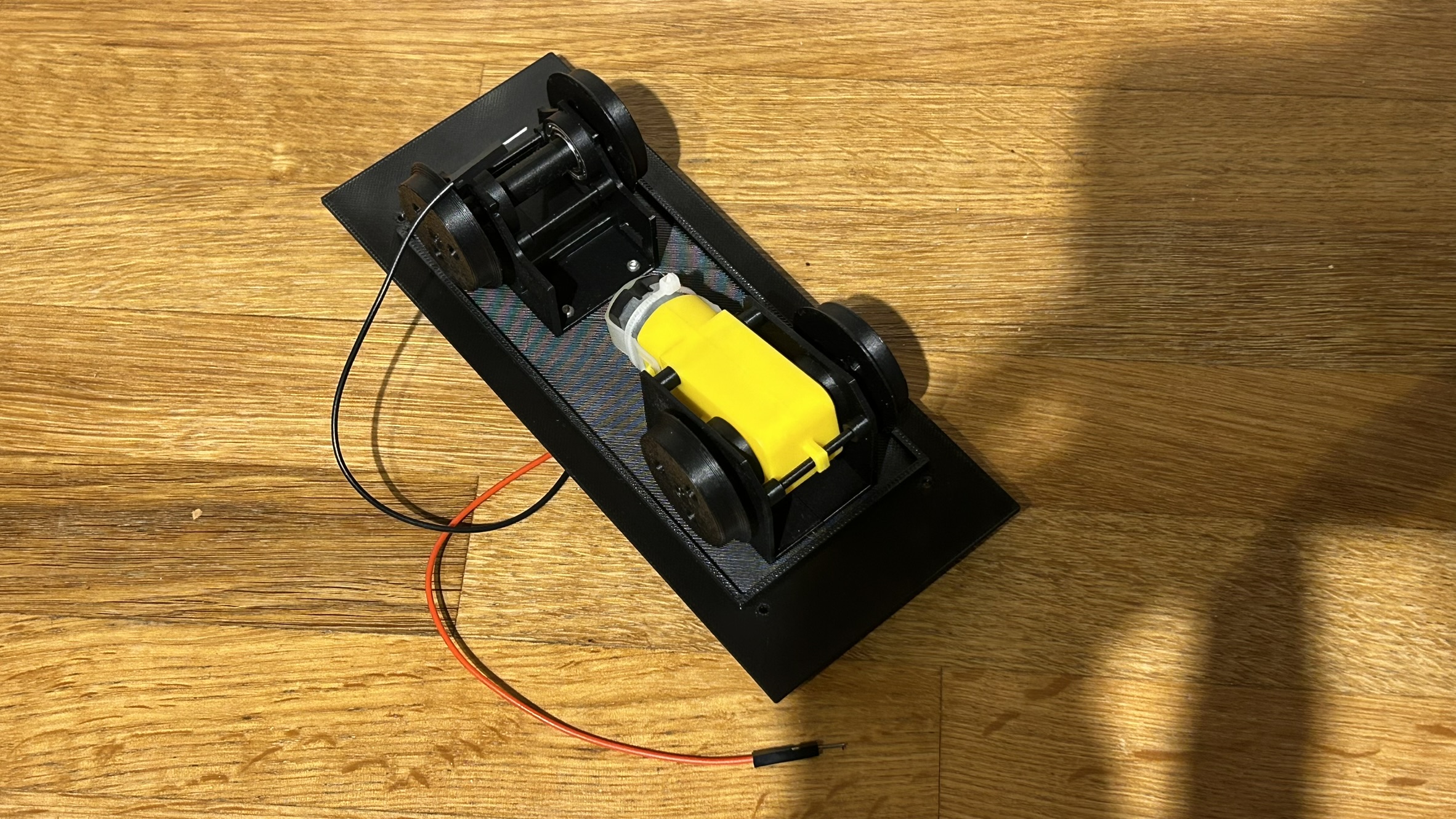
The stub axles on the motor block are fixed to the motor spindle by M2.5 countersunk screws down the bore.
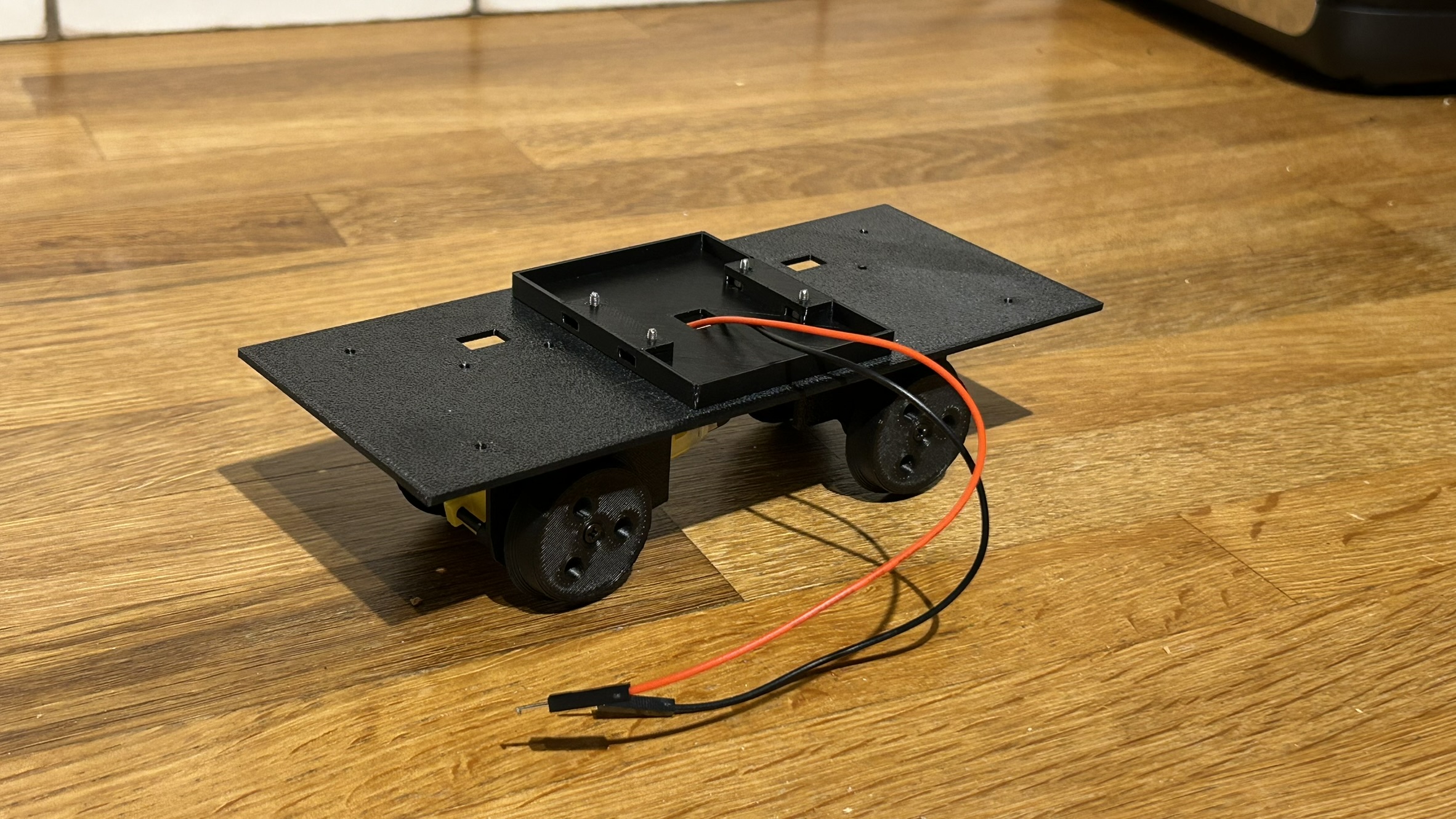
At this point, applying 3.7v to the motor had it moving around nicely!
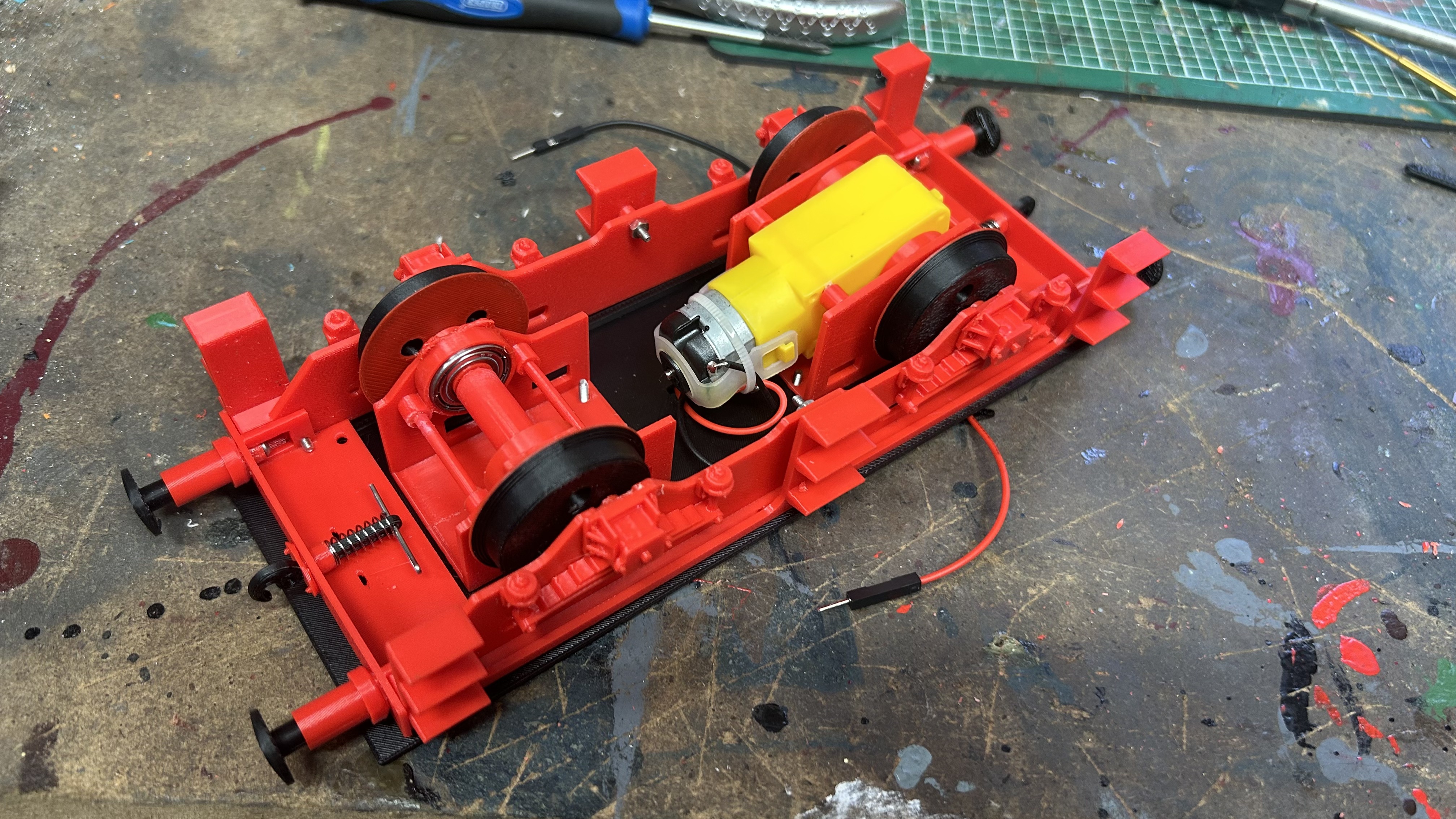
This picture shows the kiddie loco and better illustrates the blocks, bearings and dummy axle. When locomotive parts have a colour change on the angle of print, it’s always nice to take advantage of the filament swap on my printer – so the wheels on the kiddie version have red inners.
Note that the middle chassis stretcher is removed/replaced with bolts – it would foul the motor.
idler block
The idler block uses exactly the same design as the motor block, albeit with an idler axle in place of the motor into which the stub axles fit.
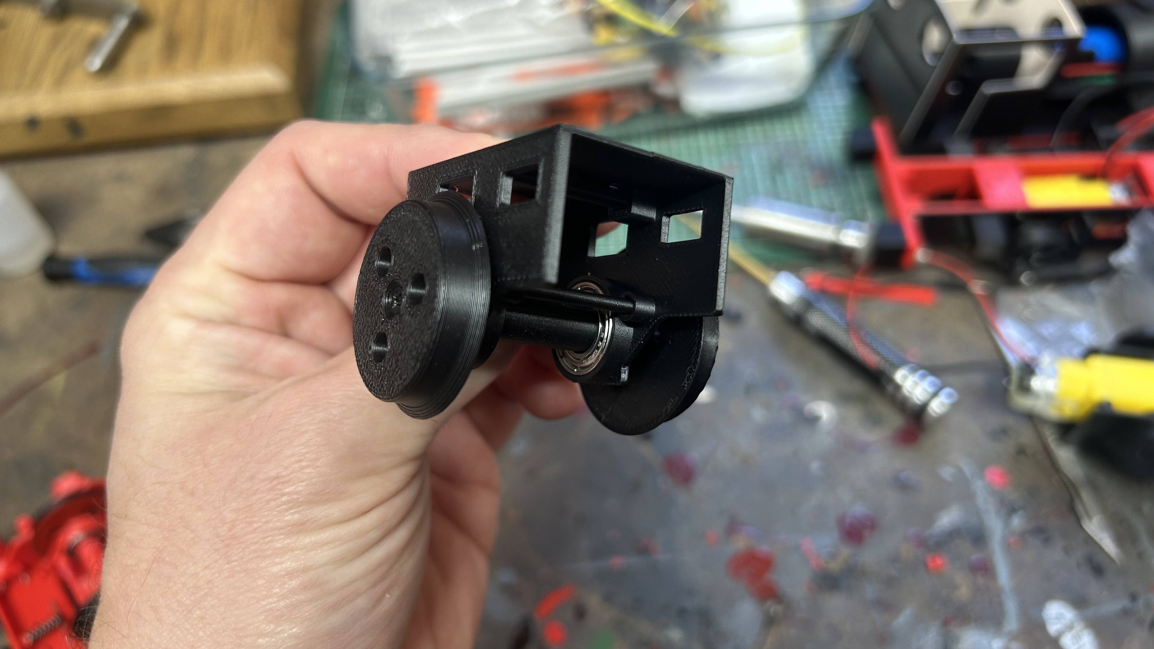
Should the wheels/motor/blocks need to be replaced or serviced, it’s a simple process to flip the locomotive over and unscrew the blocks, disconnect the JST connector between the motor and ESC (being careful that now the inner floor of the loco is loose – maybe best to do one block at a time and replace those screws removed as you go!)
bearings
Taking inspiration from the LYR Pug design, my motor/idler blocks use 16mm OD, 8mm ID, 5mm thickness roller bearings (code W688ZZ) – these are large enough to accomodate stub axles that are thick enough to enshroud the ends of the motor shaft.
To keep things simple, the idler axle has the same diameter, fixing points and alignment pins as the geared motor, so no unique parts are required except the dummy centre section of the axle.
Bearings such as these are overkill, but are cheaply sourced alongside the other proprietary parts.
Battery, electronics, etc.
There is no documentation the proposed original electronics for the LYR Battery Electric that I can find, simply a couple of motorisation options.
You are of course at liberty to choose your own system, but I would like to discuss what I have done.
original electronics
On my original model I used a simple roof-mounted DPDT switch wired to a 4xAA battery pack and a single geared N20 motor. This was very slow and incredibly weak – barely able to shift two mineral wagons at a crawl, so with a little trial and error I worked on a new circuit.
Revised electronics
The following diagram illustrates the circuit used for the RC version of the LYR Battery Electric – while it may look a little complex, it’s simply daisy-chaining tiny, off-the-shelf components together for the desired result.
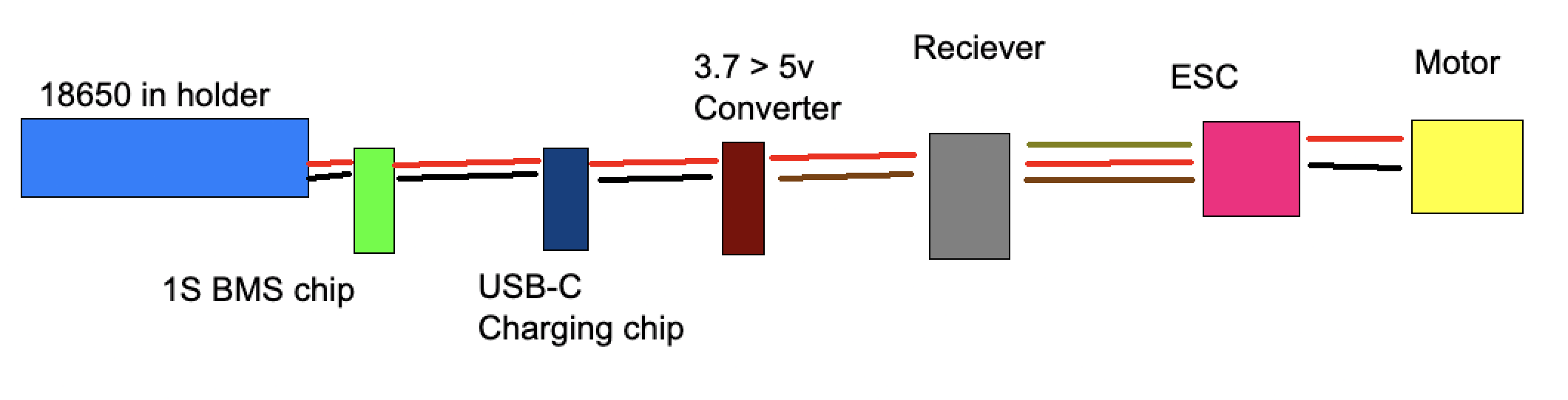
Only the first two chips are required for the kiddy version!
I should also add that I put a small SPST switch between the BMS and USB-C charging chip after this diagram was created, to have a hard ‘power off’ control for the RC version.
Battery
An 18650 battery sits in a holder – it’s not “protected” which is very dangerous for a Lithium battery, so the terminals are connected to a “Battery Management System” chip – which monitors and protects the battery – by wiring the positive and negative wires from the holder to the B+/B- terminals of the BMS.
USB-C charger
There are affordable USB-C chargers for Lithium batteries – a common variant has connectors for a battery, and for an onward load. Theoretically you might want to switch-out the charger circuit, but testing by Mr D. Viewing suggests there is very little ‘leak’ by leaving it in-line and my circuit does this – the wires from the BMS go to the battery terminals.
Kiddies version (with switch)
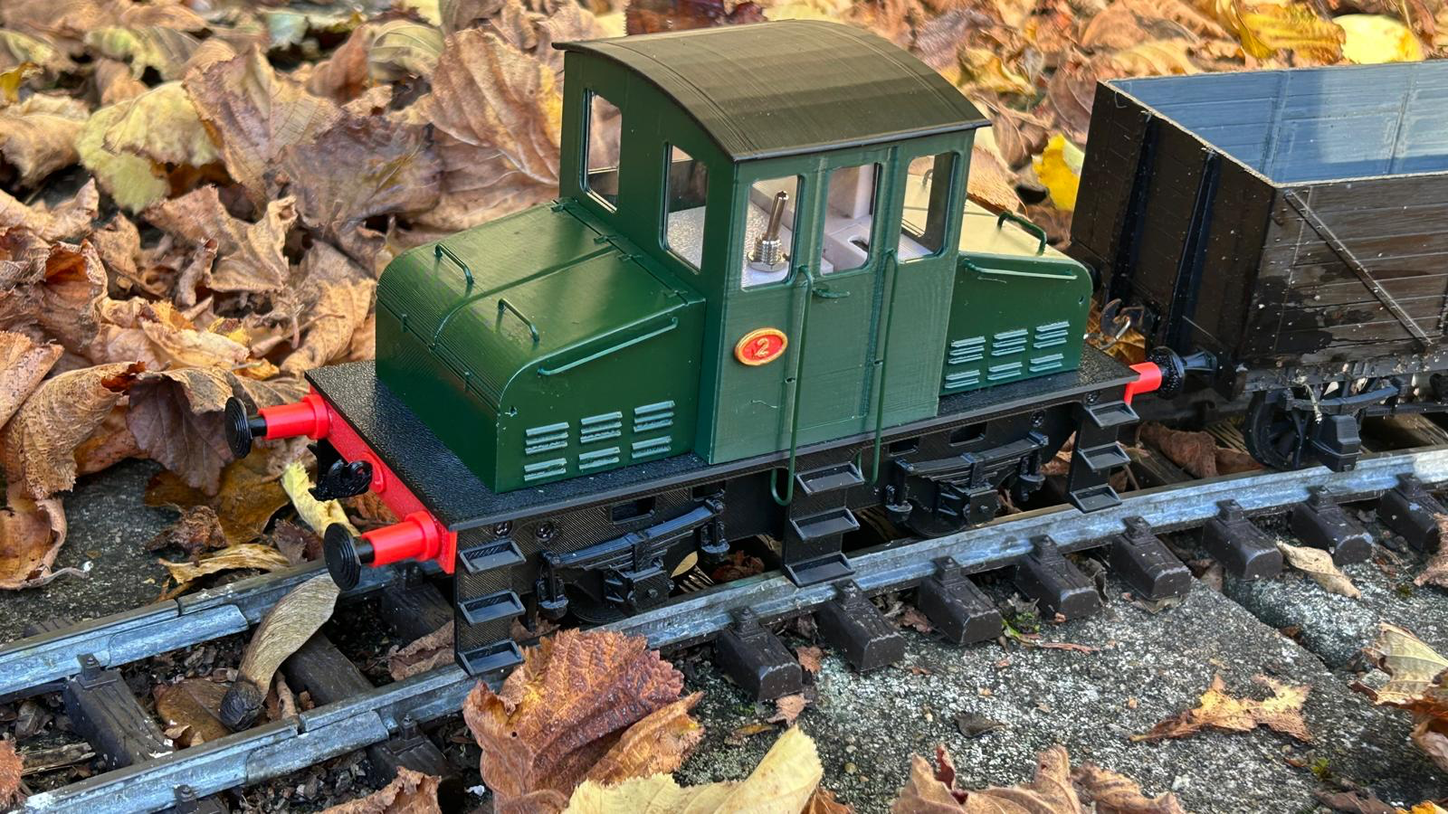
At this point, you can simply connect the wires to the motor and get the locomotive moving. For my ‘kiddies’ version, I ran the output wires up from the charger to the roof with a DPDT switch and then down to the motor – so direction can be toggled.
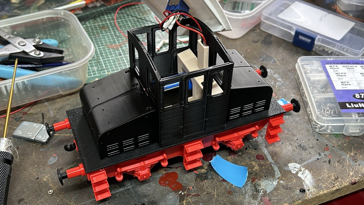
The photograph above shows the wiring for a DPDT ‘kiddies’ version, with the blue 18650 visible in the cab, and the USB charging port visible on the ‘desk’ of the control panel.
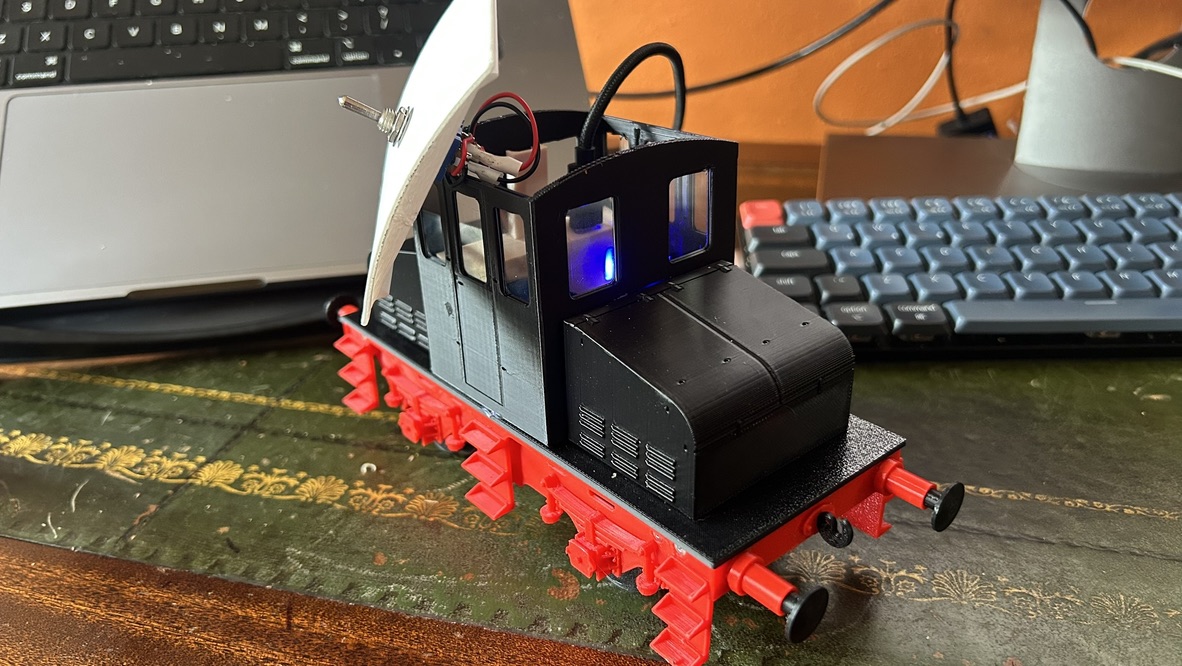
A slot in the front of desk shows blue at full charge and red when the battery is charging.
This example uses a roof-mounted toggle-switch instead of an RC reciever, for little fingers to fiddle with around the Christmas tree.
Remote control version
For remote-control, one can benefit from a slightly higher voltage, and needs to include both a speed controller and RC receiver – and an on/off switch!
3.7v to 5v Converter
From the output terminals of the USB-C charger I have placed a DC-DC converter, to up-rate the voltage from 3.7v to 5v. The converter can manage up to 12v, but for the rest of the electronics, a stable 5v is perfect. In my case this involved removing two tiny resistors on the chip – and I validated the output voltage using a multimeter across the output terminals before connecting anything else.
5v power Servo Lead
We are using a tiny ESC which needs to be receiver-powered (rather than being directly connected to a battery) – so we need to supply 5v to the RC receiver instead.
The receiver has multiple function sockets, designed to take 3-pin servo leads – each servo-lead socket has a positive, negative and signal connection, so I wired the DC-DC converter output to the +/- of a servo cable (and removed the ‘signal’ other pin/wire).
Receiver
I used the HotRC FC-06a reciever for this (and many other) builds, it’s a affordable and simple – and so the servo cable plugs in to one of the function sockets – they all share power.
Theoretically you can now test charging, powering up the receiver and binding it to a transmitter.
Electronic speed controller
For this little locomotive, which uses a 3-6v cheap yellow geared motor – an expensive and powerful ESC was not required, so a simple 1S ESC from AliExpress did the job. The ESC has a servo lead on one end which plugs into the HotRC Receiver (I use channel 2, which corresponds to forward/backward on the controller) and the other is wired to the motor. For the sake of keeping things detachable – via a two-pin JST connector.
Switching
Lastly, I added a switch on a removable cover for the battery which cuts the positive connection from the battery to the USB charger (and thus the rest of the electronics).
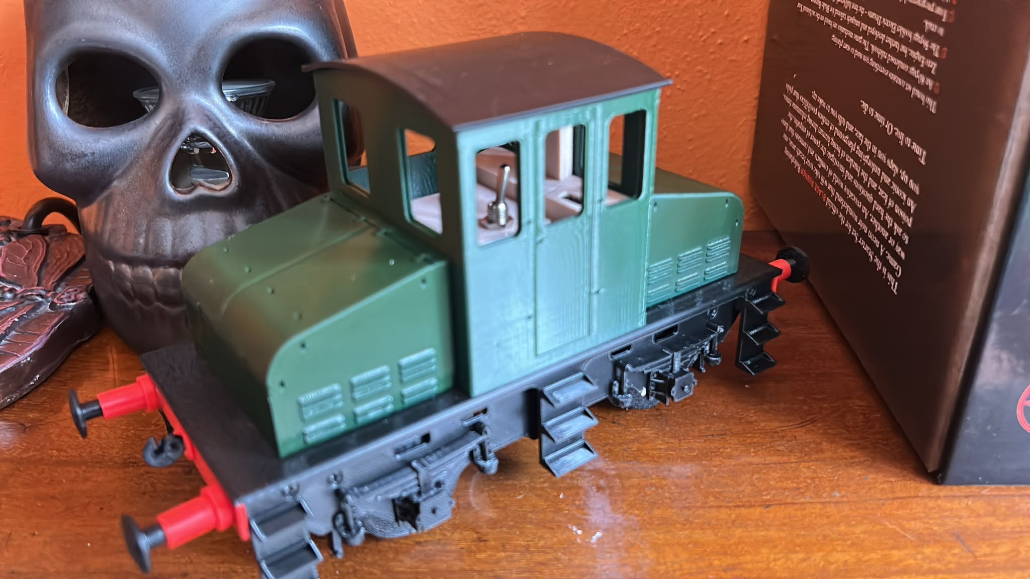
Visible through the windows is the on-off switch and USB charging port.
Motor
The motor is a simple yellow plastic hobby motor – it’s not designed for heavy or sustained use, but neither of these are major factors for me!
Finished Electronics
All of the electronics fit easily in one bonnet, with the other available for weight/etc. using adhesive balance weights for car tyres.
Finishing and final Details
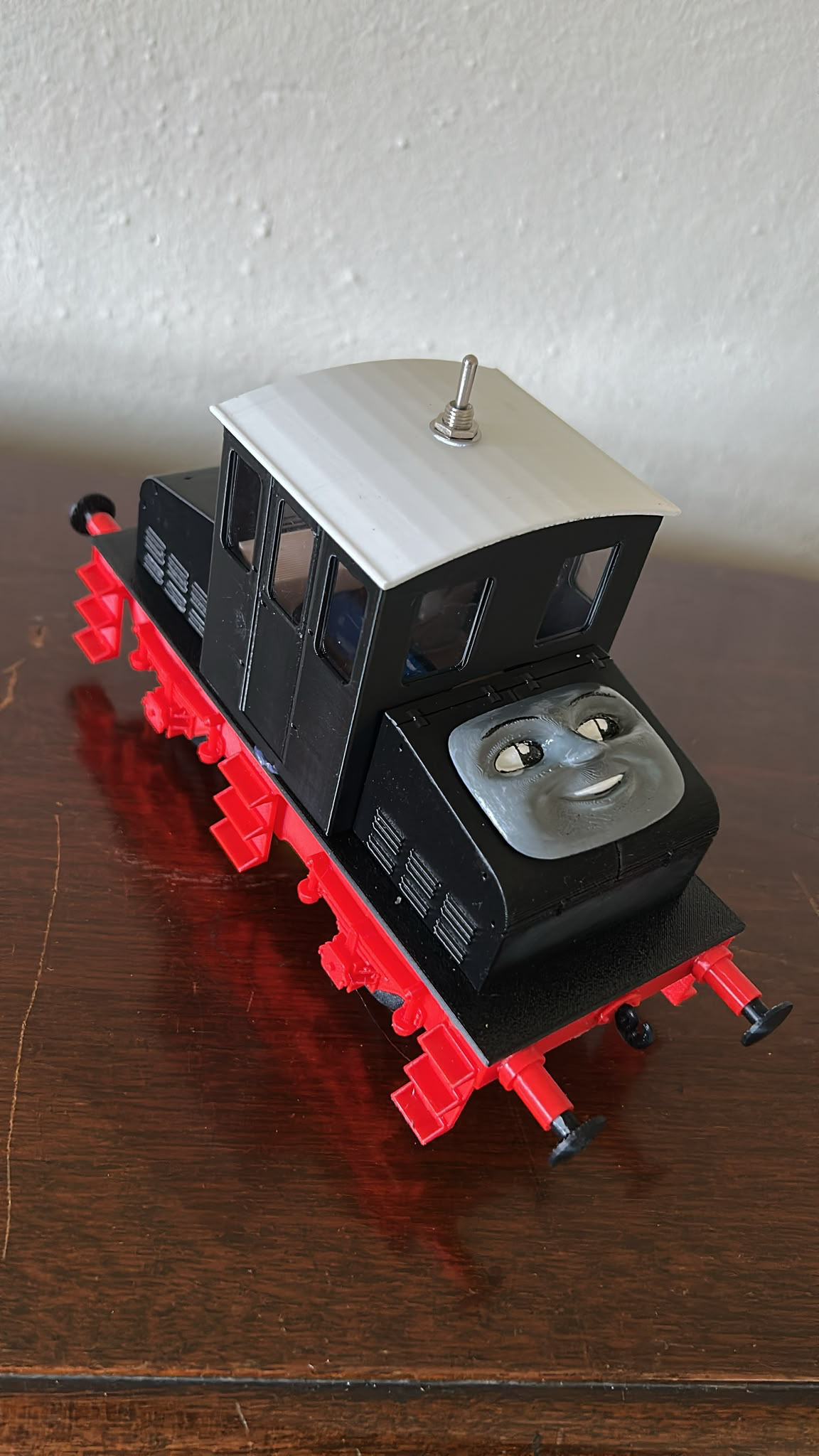
Thomas Face
For the kiddy version, I used a ‘Stanley’ face from Thomas the Tank Engine suitably squished and printed at 0.08mm resolution, painted Myford Grey and Satin White, with a Pentel black ink pen for the eyes and eyebrows
Sprung Buffers
Though clearly accounted for, I could find no detail on the buffer and spring arrangement – there is an 18mm M2 button-head screw which passes through the buffer shank, through a 0.2mm x 2.5mm x 12mm compression spring and then into the back of the buffer – the whole assembly is made on the bench, and then the shank itself is cemented into the buffer beam.
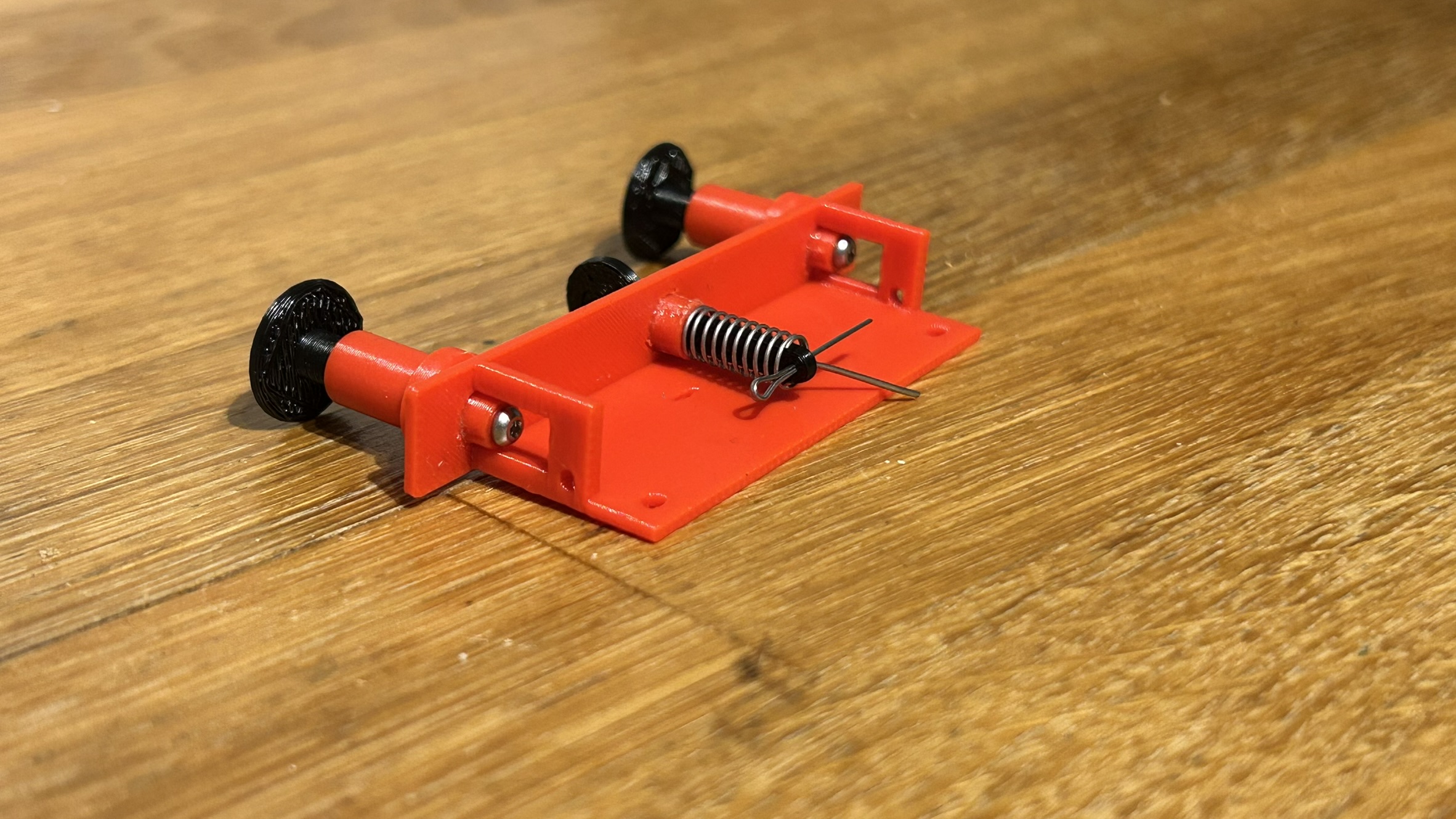
You need to clear the bores of the buffer housings with a 2.2mm / M2 clearance bit.
Sprung hook
The coupling hook itself is also readily sprung – simply using an 0.4mm x 4mm x 12mm compression spring and a small split pin on the hook shank behind the buffer beam. This could be an obvious candidate for a filament-based spring – but for now this is good enough!
I haven’t got around to adding hooks, but I understand that soft iron wire
Windows
Both engines got 0.5mm PETG windows which insert from above.
Painting
The ‘kiddies’ loco was left in filament colours.
The ‘adult’ loco was printed in green filament which had a dusting of Brooklands Green aerosol, and grab-handles were added from 0.8mm and 1mm brass rod, bent up using the supplied jigs.
The LYR ‘No 2’ plates were printed in red and the border/number touched up in brass.
Handles
The original model specified bent brass rod for the grab handles and provided bending jigs for forming them – however, I was unable to get a properly satisfactory result. I think this may be due to the springiness of brass wire, which requires ‘overbending’ to spring back to the right-angles desired.
I decided to take inspiration from the Mr T. Walder’s Brake Van and use printed rails, using the measurements provided in the instructions to create pre-formed handles.
Though these handles would work with a 0.4mm nozzle, I swapped to a 0.2mm nozzle for these parts. They are very flexible, and should stand up to handling, but I have fixed them with PVA just incase they do snap off!
Final Thoughts
I am now at the point where I’ve spent quite a few hours designing and building two of these engines and many many iterations of the internal electronics components and printed insert – there are obviously things I would do better next time and inevitably additional QoL changes I would make:
Power LEd / Lamps
A lamp with an LED on the footplate to indicate whether the unit is turned on. This could be facilitated through a simple 5v-compatible LED attached to a servo lead and inserted into one of the Receiver function plugs.
Electronics balancing
Splitting the electronics between the fore and aft bonnets – The original set of 3D printed components was meant to be an insert to Mr. M. High’s standard floor, so I was somewhat restricted if I wanted to maximise open space in the cab, but I recognise that was a fool’s errand and longer channels to permit the RC gear under the non-driven end would have created more space.
Holistic Design
As my first real effort in creating both my own RC circuit and my own way of mounting and arranging it, I worked iteratively without real foresight on the final product. Overall while I’m satisfied with the result, I’m sure my next will be far more straightforward!


You must be logged in to post a comment.